Crimping instructions » How to achieve the perfect press connection for an electrical contact
This text is machine translated.
Published: 11.10.2022 | Reading time: 9 minutes
It wasn't so long ago that electrical connectors were soldered to the corresponding cables in laborious manual work. However, this work took a very long time and the soldered joints very often led to cable breakage. It was also quickly recognized that it was not advantageous to solder fine-stranded wires before mounting them in screw terminals. The soldered joints give way over time, causing the terminal screws to become loose. The resulting deterioration in contact led to dangerous overheating of the compression fitting.
Crimping was developed as an alternative to soldering. The driving force behind this was the automotive industry. This was because the increasingly complex vehicle electrics required more and more cables and connectors in new vehicles. The automation of the crimping process also eliminated the need for time-consuming manual work. With automatic crimping machines, it is now possible to produce pre-assembled cables with durable, high-quality connections in large quantities and in a short time.
However, manual crimping with crimping pliers also results in perfect contacting with every correct application. We explain how to crimp connectors correctly and are happy to provide you with further information on the subject of crimping.
The term "crimping" refers to the forceful compression of a sleeve to create a mechanically strong connection between two components. The name of this processing method has been adopted from the English language and means to press, fold, deform, squeeze or crimp. Crimping pliers are sometimes also referred to as cable lug pliers or pressing pliers.
When connectors have to be attached to electrical conductors in electrical installations or vehicle construction, the process is called crimping.
Connectors on hose lines or plastic pipelines are crimped on by specialists. Wire end ferrules, for example, are referred to as both crimping and crimping.
The fit must be right
When crimping, it is important that the materials to be crimped match each other. When crimping cable lugs, connector plugs or wire end ferrules, the sleeve must be designed for the cable cross-section.
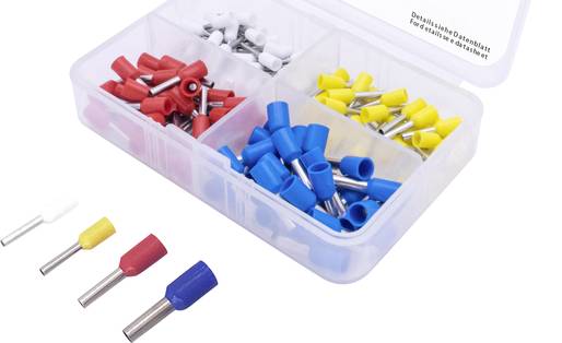
Color codes are used to make it easier to assign the sleeves of crimp connectors to the respective cable cross-section.
The plastic insulation of insulated connectors and wire end ferrules is designed in the corresponding color. This allows users to see at a glance which cable cross-section the respective crimp sleeve or connector is designed for.
Color code table for insulated single wire end ferrules
| Cross-section | German color code | DIN standard 46228 | French color code |
|---|---|---|---|
| 0,14 mm² | Gray | Gray | Brown |
| 0,25 mm² | Light blue | Yellow | Violet |
| 0,34 mm² | Turquoise | Turquoise | Pink |
| 0,50 mm² | Orange | White | Weiß |
| 0,75 mm² | Weiß | Grau | Blue |
| 1,00 mm² | Yellow | Red | Red |
| 1,50 mm² | Red | Black | Black |
| 2,50 mm² | Blue | Blau | Grau |
| 4,00 mm² | Grau | Gray | Orange |
| 6,00 mm² | Black | Yellow | Green |
| 10,0 mm² | Ivory | Red | Brown |
| 16,0 mm² | Green | Blue | Ivory |
| 25,0 mm² | Brown | Yellow | Black |
| 35,0 mm² | Beige | Red | Red |
| 50,0 mm | Olive | Blue | Blue |
Color markings on crimping pliers
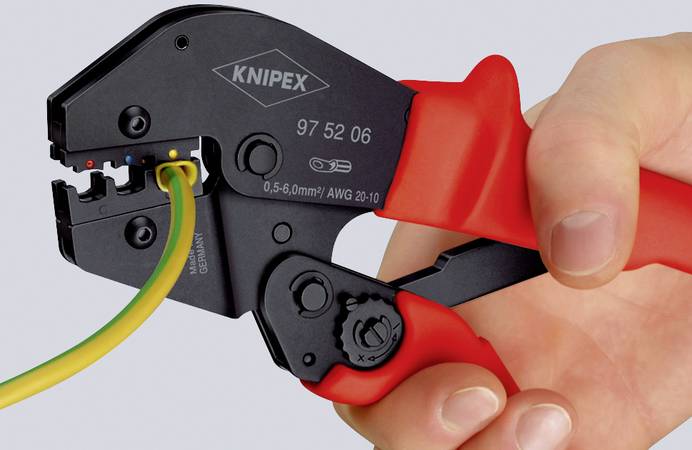
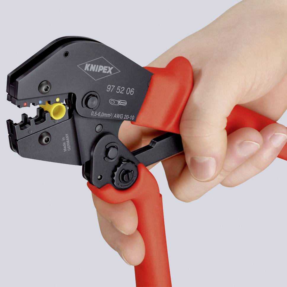
However, the tool and the tool settings must also be perfectly matched to the materials to be crimped. This is the only way to achieve a secure, force-fit connection. This is why some crimping pliers or wire-end ferrule pliers also have colored markings to ensure that the ferrules are processed with the correct crimping tool.
Knipex crimping tool with color coding for insulated cable lugs
As already mentioned, connectors, wire end ferrules or insulated and uninsulated cable lugs are crimped. However, this is only necessary if it is a flexible stranded cable in which many individual wires are used per conductor.
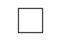
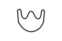
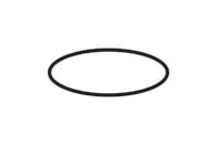
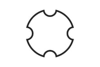
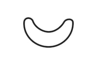
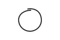
Crimping is not necessary for a rigid installation cable that only has one solid copper wire per conductor. With finely stranded wires, the individual wires per conductor must be grouped together and enclosed in a sleeve. The sleeve can be formed into different shapes during the crimping process. For a better overview, we have listed the most common crimp shapes for you:
Simplified crimp shapes
Which crimp shape fits which connector?
Die Crimphülse und der Klemmkontakt sind entscheidend
Which crimp shape you choose depends primarily on the crimp barrel or the connector. However, not every crimp sleeve can be formed into any shape.
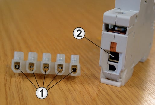
In the case of ferrules, the mechanical structure of the terminal connection also plays an important role. For luster terminals with their circular openings (1), the O-crimp, the hexagonal crimp or the trapezoidal crimp are suitable.
For circuit breakers with so-called elevator terminals (2), the square crimp offers the largest contact surfaces and is therefore the best choice.
The most common crimp shapes at a glance
Of course, the tool must also support the required crimp shape. We have listed possible combinations using a few selected and tried-and-tested connectors and ferrules.
*In the case of uninsulated compression cable lugs and compression connectors that do not comply with DIN 46235 / DIN 46267, sharp-edged wings may form on the sides of the hexagonal crimp due to overpressing. In this case, the "mandrel" crimp shape should be used. Even with thick-walled connectors, overpressing cannot occur.
Differentiation between open and closed crimp sleeves
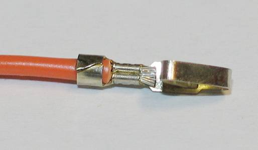
When crimping, the individual wires of a stranded cable are first enclosed in the crimp sleeve. The closed crimp sleeves are pushed onto the stripped cable ends, whereas with the open crimp sleeves, the stripped cable ends are pushed on or inserted.
In addition, some connectors also offer the option of making an insulation fixing during the crimping process. For this purpose, all individual wires are pressed into the sleeve at the front in the contact area. In the rear area, the insulation of the cable is enclosed and also pressed. However, the crimping process or the shape of the insulation fixation is not as pronounced and adapted to the insulation of the cable (see also section on crimping errors). This is important so that the insulation of the cable is not damaged and the dielectric strength is maintained.
As simple as the crimping process may seem at first, the points that need to be observed are just as important:
1. Conductor cross-section
First of all, the cross-section of the fine-wire cable must be checked. Consequently, the crimp sleeve or plug contact must also be designed for this wire cross-section.
2. Stripping length
When stripping the cable, the length of the exposed wires must exactly match the design of the crimp sleeve or connector. The bare cable ends must be neither too long nor too short.
3. Crimp shape
Depending on the crimp barrel used and the application, the appropriate crimp shape (e.g. square, hexagonal or folded crimp) must be determined.
4. Crimping tool
Once the crimping shape has been determined, the appropriate crimping tool must of course also be used.
5. correct execution of the crimping
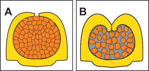
With this "gas-tight" crimping, oxidation between the individual wires and therefore an increase in contact resistance is virtually impossible. The individual wires are firmly seated in the crimp area and would break off irregularly if the electrical connection were to be pulled out.
If the crimping area is not properly filled because the sleeve was too large or the pressure during crimping was too low, a gap will remain between the individual wires (see sketch B).
In this case, the contact resistance of the crimping point would be higher from the start and there is a risk of oxidation of the individual wires. This would lead to a further increase in resistance.
As already shown, there are a wide variety of sleeves and plug contacts that can be crimped into different shapes. As a result, there are also a wide variety of pliers that are used for crimping and pressing. This is because each crimping tool is only suitable for a specific type of crimp sleeve.
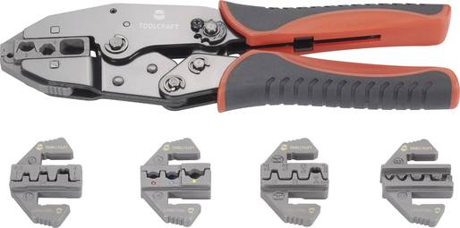
To ensure reliable plastic deformation during crimping, the right pliers for the sleeve must always be used. If, for example, blade terminals are to be crimped, ferrules cannot be crimped with these pliers. However, crimping pliers with practical interchangeable inserts are available so that the number of pliers for the different crimp connections is not too large. Depending on requirements, the insert can be changed quickly and a wide variety of ferrules can be crimped in excellent quality with just one pair of pliers. Further information on this topic can be found in our guide to crimping pliers.
Some popular and frequently selected crimping pliers
Probably the most common mistake made when crimping is an incorrect assignment of cable cross-section and crimp sleeve. This leads to incorrect filling. The crimping area is then either overfilled (sketch A) or insufficiently filled (sketch B).
However, errors can still occur during crimping even if the allocation is correct. Most errors occur when crimping plug contacts with insulation fixing. However, these errors can be easily detected after the crimping process by means of a simple visual inspection.
Correct execution
Resolder crimping point
However, the cardinal mistake that is unfortunately made time and again is the subsequent soldering of a crimp connection. Some users want to do it particularly well and solder the crimping point additionally. This is unnecessary and does more harm than good.
The heat easily damages the cable insulation and has a negative effect on the material of the contact. The flux required for soldering can electrically insulate the contact area of the connector and lead to corrosion. As a result, the function of the plug connection is no longer guaranteed.
Hot solder flows under the insulation area due to the capillary effect and hardens this area. In combination with vibrations, it is then only a matter of time before the predetermined breaking point created in this way (see circle marking) lives up to its name.
Preparing cables for installation
When manufacturing an individual patch cable or for repair purposes, it is often necessary to attach the required RJ45 plugs to the cable yourself. Depending on the design of the RJ45 connector and the cable used, the steps required for this vary slightly. In principle, however, the anti-kink sleeve must first be pushed onto the cable for all plugs. The cable sheathing is then removed. A special cutting tool that does not damage either the shielding or the core insulation is suitable for stripping.
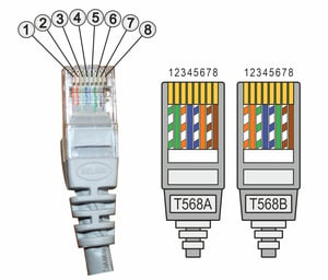
The cable shielding is then folded back and the core shielding removed if necessary. The colored insulated wires are then inserted into the plug and shortened to the required length using a side cutter. Where which wire is connected depends on the standard used in the LAN network (T568A or T568B). You can find more information on this in our guide Patching network sockets.
Carry out assembly
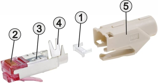
Some RJ45 plugs come with threading aids (1) that make it much easier to insert the wires into the plug. During the subsequent crimping process, the eight cutting contacts (2) of the plug are pressed onto the eight wires using RJ45 crimping pliers. If a shielded RJ45 plug is used, the plug housing (3) must be in contact with the cable shielding. This is done either when the cable is inserted or using additional clamping devices (4) on the connector housing. Finally, the anti-kink sleeve (5) is pushed onto the plug. The function of the patch cable or each individual contact of the RJ45 plug can be tested using a suitable cable tester.
If required, many examples can be found on the relevant video portals in which the crimping of network cables is explained and shown in great detail.
Note:
Although the contacts are pressed onto the cables when installing an RJ45 plug, even experts refer to this tool as an RJ45 crimping tool. However, there are now also RJ45 plugs on the market that enable tool-free installation without special crimping tools. As the simultaneous contacting of eight wires with the insulation displacement connection technology requires a certain amount of force, crimping pliers provide the best crimping results as a suitable tool.
If required, special RJ45 plugs are also available for network installation cables, which also enable a reliable connection with the rigid wires.
