Calculate cable cross-section » Correctly dimension cables & lines
This text is machine translated.
Published: 16.11.2022 | Reading time: 9 minutes
Power transmission is an important and equally tricky issue. Because even if the power comes from the socket, the socket is not always where you need it. Fortunately, there are very practical extension cables that can help quickly and easily. Very few people think about the wire cross-section of these cables, as this plays a rather minor role in this case. The extension cable manufacturers know exactly which cable cross-section is required for which cable length.
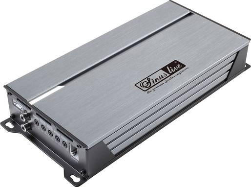
The situation is different if, for example, a powerful amplifier is to be installed in a vehicle. In this case, the cross-section of the power cable plays an enormously important role. We will be happy to explain to you what needs to be taken into account and how the required cable cross-section is calculated.
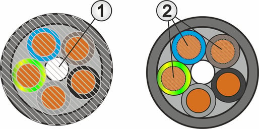
In German, the terms "Kabel" and "Leitung" are used synonymously. This usually also applies to the terms "cable cross-section", "line cross-section" and "conductor cross-section". But strictly speaking, there are clear differences here. This is because the cable cross-section or conductor cross-section represents the complete cross-sectional area of the entire cable including insulation and sheathing (1). The resulting diameter is important if a hole of the required size is to be drilled for the cable.
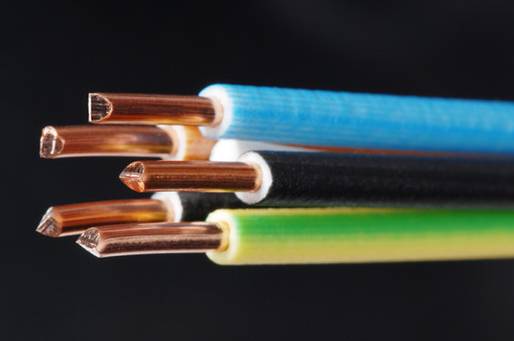
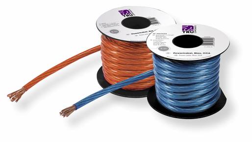
The conductor cross-section, on the other hand, refers to the cross-sectional area of the electrical conductor or the individual cores (2). It does not matter whether the cores are a single solid copper wire (see cover picture) or, in the case of a flexible stranded wire, many wafer-thin individual wires that have been combined to form a core.
If a cable is cut cleanly at right angles to the longitudinal direction using a fine saw, circular cut surfaces are created on the cores. The visible cut surfaces of the individual conductors then represent the core cross-section, which is very often referred to as the cable cross-section.
If a side cutter is used to cut the power cable, no circular cut surfaces are formed. Instead, the individual cores are crushed when the cable is cut, which can quickly lead to a misjudgement of the core cross-section.
From diameter to conductor cross-section
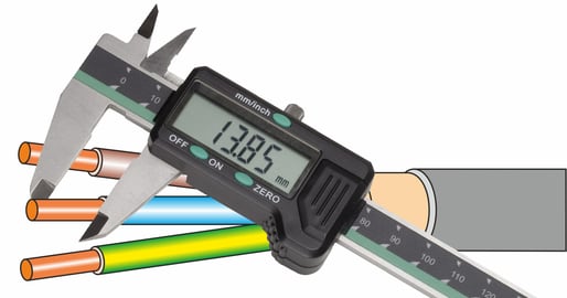
The cross-section of a conductor can be easily checked by determining the diameter of the live wires in a de-energized state using a caliper gauge.
Using the formula for calculating a circular area (A = r2 - π), the cross-sectional area can then be calculated from the diameter.
For comparison, we have listed the standardized cable cross-sections or core cross-sections of frequently used wires and cables, as well as the corresponding core diameters in the following table:
Wire diameter and wire cross-section overview tables
| Core diameter in mm | Core cross-section in mm² |
|---|---|
| 0,56 | 0,25 |
| 0,67 | 0,35 |
| 0,80 | 0,50 |
| 0,98 | 0,75 |
| 1,13 | 1,0 |
| 1,38 | 1,5 |
| 1,78 | 2,5 |
| Core diameter in mm | Core cross-section in mm² |
|---|---|
| 2,26 | 4,0 |
| 2,76 | 6,0 |
| 3,57 | 10 |
| 4,51 | 16 |
| 5,64 | 25 |
| 6,68 | 35 |
| 7,98 | 50 |
An electrical conductor can be compared to a water pipe. The larger the diameter of the pipe, the more water can flow through it. It is the same with a power cable. The larger the diameter and therefore the cross-section of the conductor, the higher the maximum current carrying capacity. This is because the larger the cross-section, the lower the electrical resistance (R) of the conductor and the resulting voltage drop.
Thin cable or thick cable - a small calculation example
A copper cable for connecting a sound power amplifier in a car with a 12 V electrical system has a length of 10 meters (5 m positive line and 5 m negative line). With a conductor cross-section of 10 mm², both cables together have an average resistance of 0.017 Ω. The same cable with 25 mm² has a resistance of only 0.0069 Ω.
If the amplifier has an output of 720 W, a maximum current (I) of 60 amperes (A) flows through both cables. Using Ohm's law R = U : I or U = R - I, the voltage drop (Ua) across the respective cables can now be calculated:
Voltage drop for a cable with a cross-section of 10 mm²
Ua = 0.017 - 60 = 1.02 V
Voltage drop for a cable with a cross-section of 25 mm²
Ua = 0.0069 - 60 = 0.41 V
Although the two cables are quite short, the voltage drop at maximum current is clearly noticeable. It must be taken into account that the voltage in a car with a combustion engine is only 12 - 14 V.
However, the voltage drop across the line and therefore the lower voltage supply to the consumer is not the main problem! In this case, the output stage merely has less power. There is no risk of damage.
The much bigger problem becomes apparent when the line losses on the two cables are considered. This is because at the high current values of 60 amps, a not inconsiderable proportion of the transmitted energy is converted into heat. The cable therefore heats up.
Power loss for a cable with a cross-section of 10 mm²
P = 1,02 V · 60 A = 61,2 W
Power loss for a cable with a cross-section of 25 mm²
P = 0,41 V · 60 A = 24,6 W
The calculation example clearly shows that the larger the cable cross-section, the lower the voltage losses and heat generation of the cable. However, the larger the cable cross-section, the higher the costs for the cable. For this reason, the optimum cable cross-section or the right cable is always a compromise. It must not be undersized, as otherwise the losses on the line will be too great and, in the worst case, there is an acute risk of fire. For cost reasons, however, an oversized cable should not be selected either.
There are several online calculators on the Internet for calculating the cable cross-section. Irrespective of this, however, it makes sense to know how the calculation works so that the correct data can be entered into a cable cross-section calculator.
In order to calculate the cable cross-sections correctly, the maximum cable length and the maximum current load must first be determined. Other important factors are the conductivity of the material and the permissible voltage drop.
There is also a separate formula for each type of voltage. The reason for this lies in the fact that with direct current, the current and the voltage are congruent (in phase).
If an inductive load, such as an electric motor, is operated on an alternating voltage, the current and voltage are out of phase with each other. The electrical efficiency or power factor decreases and this must be taken into account.
With three-phase current, the loads are operated on three phases. For this reason, the three-phase interlinking factor is used instead of double the cable length.
This results in three formulas for calculating the cable cross-section.
Direct current
A = (2 · L · I) : (𝜿 · Ua)
Alternating current
A = (2 · L · I · cosφ) : (𝜿 · Ua)
Three-phase current
A = (√3 · L · I · cosφ) : (𝜿 · Ua)
A = Cable cross-section
L = cable length in meters*
I = current in amperes
√3 = Interlinking factor three-phase current (√3 = 1.732)
𝜿 = Conductivity of the conductor in Siemens per meter (S/m)
cosφ = Electrical efficiency
Ua = Acceptable voltage drop in volts
* Note: In order to achieve a better distinction between the current (I) and the length in the formulas, a capital letter (L) was used for the length instead of the usual lower case letter (l).
Cable cross-section formulas - Important information on the specifications
Cable cross-section (A)
The cable cross-section is calculated in square millimeters (mm²). As the available cable cross-sections are graduated, the next largest value must always be used. Common cable gradations are 0.75 mm², 1.5 mm², 2.5 mm², 4 mm², 6 mm², 10 mm², 16 mm² or 25 mm². Cables with even higher cross-sections are usually only processed by specialists. However, there are also stranded wires and cables with a smaller cross-section than 0.75 mm² and in intermediate sizes.
Cable length (l)
The cable length can be measured in the classic way. For correct calculation, the distance from the voltage source to the load must always be entered, as the forward and return lines are automatically taken into account in the above formulas.
Amperage (I)
To calculate the cross-section, the maximum current load must be specified in amperes (A). The information can be found either on the rating plate of the consumer or in the technical documentation. If only the power (P) and the operating voltage (U) are specified, then the current must be calculated using the formula I = P : U. Alternatively, a current measurement can also be carried out.
Concatenation factor (√3)
With three-phase current, it is not the voltage between one phase or the outer conductor and the neutral conductor that is used, but the voltage difference between the three phases. For this reason, the formula does not use twice the cable length, but the interlinking factor. The interlinking factor of 1.732 (√3) is a fixed value that does not change regardless of the other numerical values in the formula for calculating the cable cross-section.
Conductivity of the conductor (𝜿)
The specific conductivity of the conductor (kappa) depends on the material used. Depending on purity and temperature, copper has a conductivity of 58 Siemens per meter (S/m). Silver has a significantly better conductivity of 62 S/m. At 37 S/m, aluminum is even lower than the other two materials. The reciprocal value of conductivity is also referred to as specific resistance. With a conductivity of 58 S/m, the specific resistance ρ (Rho) would be 0.0172 (Ω/m).
Electrical efficiency (cosφ)
The electrical efficiency of an AC consumer indicates the ratio between active power and apparent power. The required information can be read directly from the rating plate of a motor or taken from the technical data sheets. For direct current systems, the value for the electrical efficiency is always 1 and can therefore be ignored in the formula.
Acceptable voltage drop (Ua)
The acceptable voltage drop indicates by how much the operating voltage may be reduced due to the line resistance. For critical loads such as chargers or power supply units, the voltage drop should not exceed 2%. For non-critical loads such as a lamp, the acceptable voltage drop can be up to a maximum of 4%. In some cases, the formulas for calculating the cross-section do not require the voltage drop in volts, but the factor of the deviation (e.g. 0.02 for 2%) and the level of the operating voltage. If both values are multiplied, the result is the acceptable voltage drop.
Our calculation example involves the audio power amplifier mentioned above, which is to be installed in the trunk of a vehicle. The power amplifier is operated from the 12 V vehicle electrical system and has an output of 720 W. According to the following formula I = P : U, a maximum current of 60 A flows at 720 W power. The positive cable is connected directly to the battery and routed to the amplifier. The required length in this example is 4.5 m. The negative cable has a length of 0.5 m and is connected directly to the vehicle chassis in the trunk. The resistance of the bodywork from the trunk to the negative connection of the battery is so low that it can be neglected in this case. The total length for the outward and return cable is therefore 5 m.
Only half the distance, i.e. 2.5 m, is entered in the formula, as this value is multiplied by two and therefore the actual cable length is taken into account in the calculation. The maximum voltage drop must not exceed 2% of 12 V, i.e. 0.24 V. The required cable cross-section can now be calculated using these values:
A = (2 · L · I) : (𝜿 · Ua)
A = (2 · 2.5 · 60) : (58 · 0.24) = 300 : 13.92 = 21.55 mm²
In this case, a cable with a cross-section of 25 mm² is required.
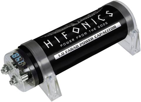
High-capacitance capacitors for line relief
By the way: Many car hi-fi enthusiasts use an ingenious trick to reduce the current on the amplifier's electrical connection cables. This is because the maximum current only flows at maximum power. This is usually only required for the bass pulses. As a result, the operating voltage of the amplifier has brief voltage dips in the rhythm of the music or the bass pulses.
To prevent this, a high-capacitance capacitor is connected in parallel to the voltage input of the amplifier. This capacitor charges up between the bass pulses and releases its energy to the amplifier during a bass pulse. This additional power source installed directly at the amplifier significantly reduces the voltage dips and the supply voltage is more stable.
For alternating current and three-phase current, the cable cross-section can be calculated using the formulas listed above and according to the same scheme as in the example with the direct current consumer. However, the result only serves as a rough guide. According to DIN VDE, there are other factors to consider when determining the cable cross-section for electrical systems or electrical devices than just the calculation result.
A very important point is the way in which the electrical cables are laid. This is because it makes a significant difference whether a power cable is laid under plaster, in an empty conduit, in a cable duct or in an open-top cable tray during electrical installation.
Other important points are the ambient temperature, the temperature resistance of the insulation and the number of loaded cores within the cable.
As there are extensive regulations in this regard that must be observed, we recommend the assistance of a specialist when selecting the right electrical installation cable.
Why are there different values for specific conductivity?
The indication of conductivity depends primarily on the purity of the conductive material and also on the temperature. For this reason, the values given for copper, for example, vary between 56 S/m and 58 S/m. In case of doubt, when calculating the required cable cross-section, the value to be used should be looked up in the technical data sheets of the cable.
What are CCA cables?
In a CCA cable, the electrical conductor is made of aluminum that has also been coated with copper. These cables are lighter and significantly cheaper than comparable models with a solid copper conductor. Due to the copper coating, the specific conductivity of a CCA cable lies between copper and aluminum. For this reason, a larger core cross-section is almost always required than with a copper conductor. Only with high-frequency AC voltage does a CCA cable have a clear advantage due to the current displacement to the outer area of a conductor (skin effect).
When must the cable cross-section be calculated?
Electrical installation specialists know the relevant regulations inside out and therefore also know which cable to use for which task and how large the prescribed cross-section must be. However, if high currents have to flow at low voltages, it is essential to calculate the required cable cross-section.
What cable cross-section is required for 12 V?
This question cannot be answered in this way, as the cable cross-section depends solely on the current and the cable length. This results in a voltage drop that should be as low as possible. At 12 V, a large car amplifier requires a cable with a cross-section of 10 mm², 20 mm² or even more, depending on the power. A low-current 5 mm LED, on the other hand, which is operated via a series resistor, can easily be connected to a 0.14 mm² cable in the car, as only a very small current flows. Regardless of whether a lot or little current flows, the appropriate fuses must always be installed in the cable.
