Detecting defects in solar modules & solar systems » Checking the PV system
Published: 10.05.2023 | Reading time: 8 minutes
This text is machine translated.
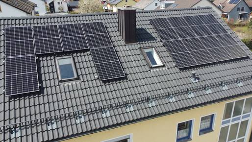
Steadily rising electricity prices, government subsidy programs for renewable energies and a rapid energy transition are making photovoltaic systems with grid feed-in increasingly interesting for private individuals. And not just for owners of electric vehicles, who can use the solar power they generate themselves to charge up for free, so to speak.
Craftsmen, companies and industrial businesses also use the available roof and open spaces to generate electricity with the power of the sun and thus reduce operating costs.
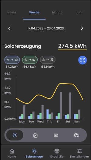
Grid feed-in inverters with intelligent electronics and a direct connection to the Internet provide a precise overview of the system's performance at all times.
Responsible persons can therefore recognize immediately if the yield drops because something is wrong with the system. We will be happy to explain to you how a photovoltaic system works and what can be done in the event of a fault to rectify the damage.
In order to be able to find the fault in the photovoltaic system quickly in the event of a malfunction, it is necessary to know the structure and function of a solar module or a complete solar system.
Solar panel
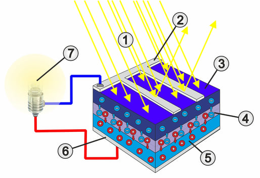
A solar panels consists of a more or less large number of photovoltaic cells. A photovoltaic cell in turn consists of two wafer-thin layers of high-purity silicon to which foreign atoms such as boron and phosphorus have been added.
Experts speak of positive doping with boron and negative doping with phosphorus.
A so-called pn junction (boundary layer) is created at the interface between the two semiconductor layers.
We have described the exact structure and function of a pn junction in detail in our guide to the 1N4148 diode.
In a solar cell, the incidence of sunlight (photons) releases electrons in the boundary layer, which generate an electrical voltage at the terminals.
Solar panel
A single solar cell with a size of 156 × 156 mm, for example, is quite capable of supplying a considerable amount of electricity in strong sunlight.
However, the electrical voltage is relatively low. With silicon, the terminal voltage of a single photovoltaic cell is around 0.5 - 0.7 V. This is why the individual solar cells are connected in series within a module. This works in a similar way to the batteries in a flashlight, which are also connected in series to increase the voltage.
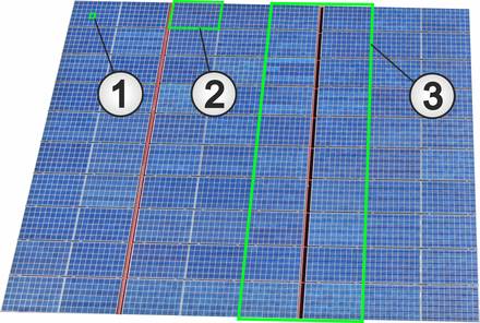
In the solar modules shown in the picture, 36 cells are connected in series to form so-called substrings. As a result, these modules achieve an open-circuit voltage (open terminals) of 24.9 V.
The cells are laminated between two foils after soldering and are thus optimally protected against moisture. An aluminum frame with glass pane and a stable rear foil with connection box complete the construction of a solar module.
Popular solar panels
Solar field
A solar field consists of several interconnected modules (2). The individual modules are connected in series to form so-called strings (3).
The number of modules connected in series depends on the space available and therefore on the possible number of modules.
It is important that the total voltage (open circuit voltage) of all modules connected in series does not exceed the input voltage of the inverter.
In order to achieve the desired output, several strings are connected in parallel in a solar field. The number of modules per string must be identical.
Inverters and energy storage
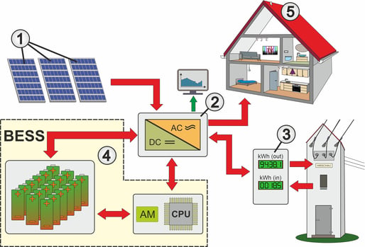
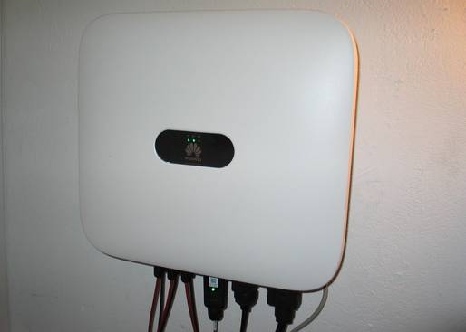
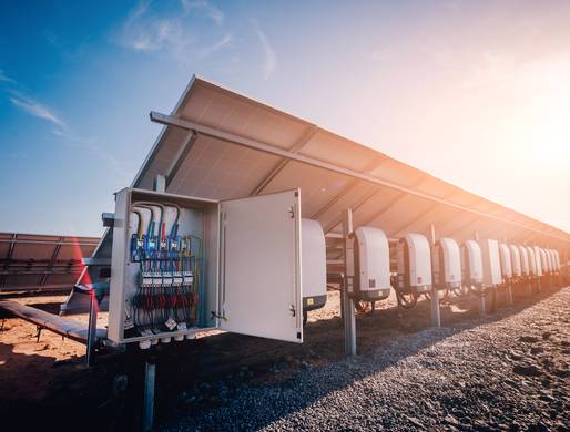
As solar modules (1) supply a direct voltage due to their design, this must be converted into an alternating voltage with the help of an inverter (2). This is the only way to feed it into the public grid or use it internally (5) via a bidirectional meter (3).
The inverters often also have a connection option for an energy storage unit (4) or Battery Energy Storage System (BESS). The energy storage system is a large battery that is charged with direct current and releases direct current again.
If the solar system supplies too little electrical energy on bad weather days or no electrical energy when it is dark, the battery serves as an energy source for the consumers before electricity is drawn from the supply grid.
The installation or purchase of a photovoltaic system represents a certain investment. Regardless of whether the system was purchased or leased. It therefore goes without saying that operators always want to keep an eye on the functionality of their system.
In the simplest and cheapest case, this is done by reading the electricity meters. The meter readings can be noted at regular intervals and then compared.
Alternatively, inverters with built-in function displays are perfect for quickly gaining an overview of the current output of the photovoltaic system. Especially if, for example, bar charts with time axes are displayed.
In the most customer-friendly version, data loggers are used to store the various characteristic values of the system. The data can then be retrieved conveniently at any time and from anywhere using a smartphone.
Regardless of the type of monitoring, meaningful empirical values can be gathered very quickly about the performance of the system in certain weather situations.
As a result, you will also notice very quickly if the output of the photovoltaic system is suddenly significantly lower or the usual high output is no longer achieved.
Our practical tip: Take degradation into account when assessing performance
Photovoltaic modules are exposed to the weather and environmental influences all year round without any protection. In addition to mechanical stress from rain, snow and hail, the modules also have to withstand high temperatures, frost and considerable UV radiation. All in all, this means that solar modules are subject to natural ageing and a reduction in performance (degradation). Crystalline solar modules lose around 10 to 15 % of their output slowly but continuously over a period of 20 - 25 years.
In order to be able to precisely localize and rectify the fault or defect later in the event of a possible malfunction, it is necessary to have complete system documentation. These documents should be requested from the system planner or the contractor during installation or at the latest during commissioning. String and circuit diagrams and the measurement logs are very helpful here, as the current values can be compared with the commissioning data in the measurement logs in the event of a fault.
Failure of the inverter
The centerpiece of every photovoltaic system with grid feed-in is the inverter.
This rather sensitive component reacts very sensitively to strong current and voltage fluctuations. However, external influences can also have a negative effect on the inverter.
If error messages are indicated by LEDs or on the display, the operating instructions should always be to hand so that the error code can be correctly assigned.
In most cases, the documents also describe all further steps that should or must be carried out by the user before calling in a specialist.
Shading and hotspots
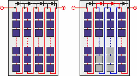
In the event of shading, the affected cells do not generate any current on the one hand and act as a disruptive resistor on the other. This significantly reduces the current yield of the module's active cells.
As the shaded cells become very hot due to the high module current, a hotspot is created which sooner or later destroys the cell.
To avoid this, manufacturers also install so-called bypass diodes in the junction boxes of the solar modules.
In this case, the diodes present a significantly lower resistance to the current than the shaded cells and short-circuit the string with the affected cells. This effectively prevents the formation of hotspots.
Gradual loss of performance
A gradual reduction in performance can, but does not necessarily have to, be related to degradation. It is also often the case that, over time, ever larger trees or bushes lead to partial shading of the solar modules.
However, large areas of stubborn dirt that can no longer be loosened and removed by rainwater can also be the cause. In this case, professional cleaning of the solar modules will significantly increase the yield again.
Different or insufficient performance of the strings
If all the strings of a photovoltaic system have the same structure and the modules are aligned in the same way, it is possible to carry out meaningful comparative measurements.
This quickly reveals whether the current in one string is lower than in the other strings.
Alternatively, the currently measured values can also be compared with the data in the measurement logs that were created during commissioning.
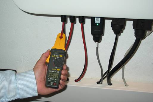
Current clamps or clamp ammeters are suitable for quick and easy current measurement because the power lines do not need to be disconnected for the measurement.
If a photovoltaic system has measurably lost power, the cause of the fault should be determined and rectified. There are different procedures for this.
Optical inspection
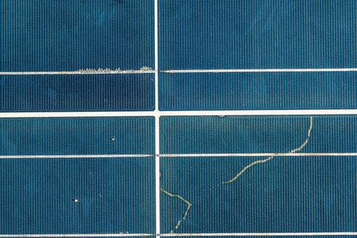
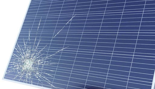
If a string has been identified as faulty, the solar modules belonging to the string must first be visually inspected. This makes it very easy to see whether, for example, hail has destroyed the glass plate or whether fine cracks have formed in the glass (so-called snail marks). Depending on the age of the damage, traces of oxidation caused by moisture penetration can also be easily detected.
Defective junction boxes or cables damaged by animal bites can also be detected quite easily during a visual inspection. Localized changes in colour or damage to the rear foil can also be an indication of possibly overheated and damaged cells.
Metrological testing
If the affected modules are visually inconspicuous and show no visible damage, a metrological examination must be carried out. In this solar module test, it makes sense to carry out several comparative measurements with identical modules in order to be able to clearly identify defective modules. The most important parameters are the open-circuit voltage and the short-circuit current if the modules are aligned identically to the sun.
For modules that no longer reach their maximum output, the bypass diodes may be the source of the fault.
If the diodes have been overloaded and have a short circuit, the substrings belonging to the diode in the modules cannot contribute to power generation. If the diodes have an interruption, faulty or shaded cells in the module are no longer bridged, which also reduces the current yield.
Defective diodes can be easily tested using a multimeter. To avoid incorrect measurements, the diodes should be removed or at least soldered on one side. We have described the procedure for measuring diodes in detail in our multimeter guide.
Our practical tip: Be careful when measuring solar systems
In contrast to the already mentioned current measurement with a clamp-on ammeter, further measurements require extensive experience in the field of electronics and solar technology. You also need to have in-depth knowledge of the associated risks and take the necessary safety measures into account. This is because in larger systems, where many modules are connected in series to form a string, voltages of several 100 V can occur even with weak solar radiation.
Thermography with thermal imaging camera
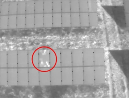
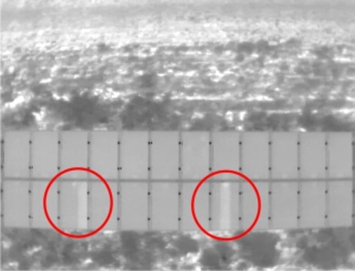
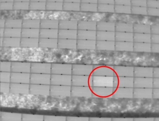
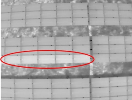
The visual and metrological inspection can of course only be carried out without great effort if the modules are easily accessible, for example in a field installation. If the modules are mounted on the roof of a tall building, inspection becomes more difficult. In this case, or in the case of extensive solar fields with a very large number of solar modules, thermography using a copter or drone has proven to be very effective.
The following thermographic images show examples of how the clearly visible differences in brightness make it easy for less experienced people to recognize the various defects in solar systems.
In order to obtain meaningful images during thermography, the global radiation should be at least 600 W per square meter or ideally 800 to 1000 W/square meter. The viewing angle to the modules or the measuring angle of the thermal imaging camera should also be 50° to 80°.
However, experience has shown that experts who carry out such drone flights with thermal imaging cameras know exactly when and how the measurements should be taken. Further steps for the repair can then be initiated on the basis of the measurement evaluations or the image material.
Whether a defective solar module can be repaired or not depends on several factors:
Type of damage
Technical faults such as damaged connecting cables, burnt connecting plugs, faulty junction boxes or even defective bypass diodes can usually be rectified quickly, easily and without great effort.
Our practical tip: Replacing bypass diodes
Important: If defective diodes need to be replaced, Schottky diodes with the required current and voltage values should always be used. This is because these diodes have a significantly lower voltage drop in the flux direction than standard silicon diodes.
It becomes more difficult if the glass plate on the top of the module is damaged. The question then arises as to whether only the glass has been damaged or also the solar cells underneath.
In this case, the current performance of the damaged solar module must first be clearly determined with the help of a measurement.
This is because if the damage is older, moisture and dirt penetrating over time will lead to oxidation of the solar cells under the glass or their connections (see also the image in the optical inspection section).
Age, size and condition
If the cause of the drop in performance cannot be clearly identified, it is necessary to check how old the module is. This is because PV manufacturers sometimes grant a very long performance guarantee on their solar modules. In case of doubt, a consultation with the seller can provide clarity.
Occasionally, the glass plate of new modules is damaged during transportation. The affected panels then still generate the maximum values for voltage and current specified in the data sheets. In this case, it is possible to seal the broken glass plate of the module with a suitable casting resin or varnish and thus save the module.
In the case of older and smaller modules, which also no longer provide full power, the cost of sealing is no longer worthwhile. In this case, replacing the defective module is the better solution. Unfortunately, however, it often happens that a module in the required size and with the required output is no longer available on the market. In this case, companies that specialize in the repair and reproduction of defective solar modules can help. Due to the constantly growing number of solar systems, both these specialist companies and experts for the installation and servicing of solar systems (solar technicians) are easy to find on the Internet.
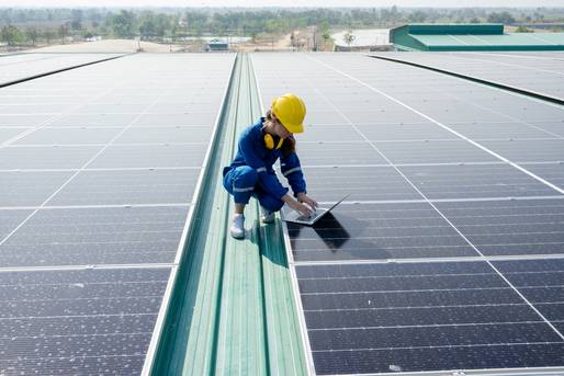
Extensive visual inspections or precise current measurements with a clamp-on ammeter are tasks that should be carried out regularly on solar installations. With a little technical expertise, these tasks are easy to accomplish.
However, if major damage to the PV system needs to be repaired, the work should be carried out by qualified specialists. Especially as the work often has to be carried out at lofty heights and requires extensive specialist knowledge.
Even though various videos on replacing defective bypass diodes or sealing defective photovoltaic modules can be found on the relevant video portals, we strongly advise against carrying out the work yourself if you lack specialist knowledge. It is better to select high-quality solar modules in advance and take out suitable photovoltaic insurance that covers all repair costs and loss of use in the event of hailstorms, for example.
