Build your own touch lamp and switch it conveniently with the DIY sensor
This text is machine translated.
Updated: 02/16/2024 | Reading time: 5 minutes
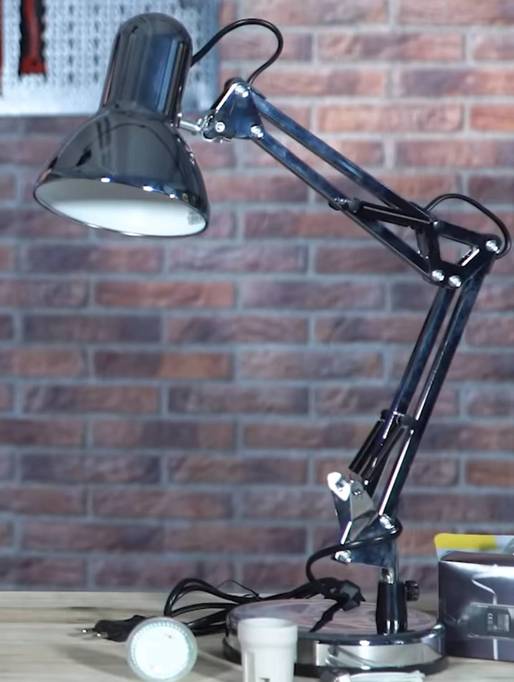
Classic desk lamps are very popular in the office, workshop or even at home. This is because they provide light exactly where it is needed at the moment.
However, they are sometimes a little awkward to operate. Especially if the switch is integrated in the supply cable and is difficult to reach behind the edge of the table. It would be great to be able to switch the desk lamp on and off simply by tapping it.
Our technology hero Simon has thought about exactly this and found a practical solution to the problem. We will be happy to explain to you how the conversion can be carried out, which parts are required and that a little manual skill is all you need.
For a lamp to be switched at the touch of a finger, the lamp must first register that it has been touched. The ripple voltage of the human body is used for this.
What is a ripple voltage?
Every electrical conductor generates an electromagnetic field when current flows through the conductor. Consequently, an electromagnetic field also builds up in the 230 V power lines used in electrical installations. Due to the alternating voltage used (230 V/50 Hz), the magnetic field changes direction 50 times per second, which corresponds to a frequency of 50 hertz (Hz).
An audio amplifier whose input is not properly shielded receives the 50 Hz oscillations of the electromagnetic field, amplifies them and then produces a clearly audible humming sound via the speakers.
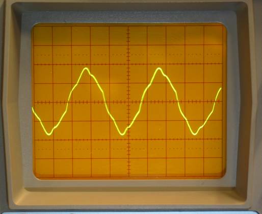
But the human body also generates a 50 Hz hum. This voltage can even be measured. All you need to do is touch the input of an oscilloscope with your fingertip. When using a 10:1 probe, voltages of around 60 Vpp can easily be measured.
However, the human body is a very poor conductor of electricity. This is why the ripple voltage quickly collapses if, for example, the ground terminal of the probe is touched with the other hand. Regardless of this, the voltage is still sufficient if the input of the sensor electronics is designed with a correspondingly high impedance.
Note: The ripple voltage of the human body is constantly present in the vicinity of power lines and is independent of the static charge. This is why the touch lamp can be switched several times in succession without any problems. In contrast, any static charge present is almost completely dissipated on first contact with an earthed body.
Our practical tip: Ripple voltage for power supply units too
The term ripple voltage is also used for power supply units. Experts use it to describe the residual ripple of the DC voltage after rectification and smoothing by capacitors. In order to keep the ripple voltage as low as possible even with high current requirements, large electrolytic capacitors with high capacitance values are preferably used in powerful power supply units.
When converting a 230 V lamp to a touch lamp, it must be electrically isolated (decoupled) from the mains supply. This means that the electrical circuit of the lamp is separated from the mains supply by an electrically non-conductive coupling, such as a transformer. For this reason, an external power supply unit is used. The touch lamp is then supplied with a DC voltage of 12 V.
It is important that the polarity of the DC voltage is observed for the circuit board still to be installed (see following section). In addition, the power supply cables must have sufficient insulation from the metal parts of the lamp.
The greatest amount of work is probably required when replacing the bulb or bulb holder. This is because the E27 screw socket of the 230 V light source must be replaced with a suitable socket for the LED light source used.
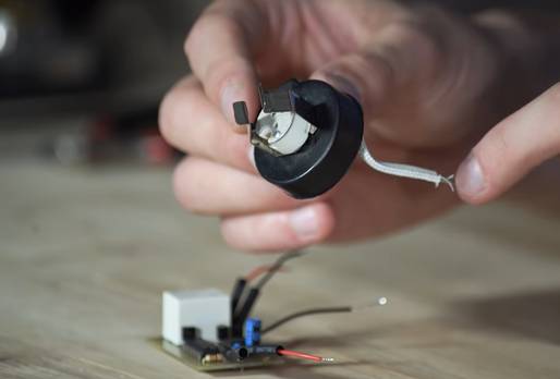
The switching function of the 12 V light source is then performed by a small circuit board with only a few components. By the way: If you are not able to etch circuit boards yourself, you can easily build the relatively simple circuit on a breadboard.
The mechanical conversion of the lamp and the replacement of the bulb holder are explained and shown in great detail in the video linked above.
In order to explain the operation of a touch lamp clearly, we have included the circuit diagram of the circuit board and a brief circuit description below.
Circuit diagram of the circuit board for the touch control
Even if the circuit diagram appears somewhat extensive at first, the function is relatively simple, which makes it easy to reproduce.
Functional description of the touch control
The power supply coming from the external power supply unit is connected to connector JP1. Even if the circuit operates in a voltage range of 5 - 12 V, a 12 V power supply unit is ideal for supplying the light source via the control board.
Connector JP2 serves as the sensor input. A cable is connected to this connector or soldering point, which establishes an electrical connection with the metal housing of the lamp. The two transistors T1 and T2 operate as a Darlington circuit. The advantage of this transistor combination is the high input resistance of transistor T1, which means that the ripple voltage is not overloaded. In addition, transistor T2 acts as a power amplifier that can easily switch the trigger input on pin 2 of the downstream IC1.
In order to generate a clearly defined switching pulse from the 50 Hz ripple voltage, the timer IC (NE555) is operated as a monostable toggle stage. We have explained the basic function of the NE555 timer IC in detail in our component guide.
The switching pulse generated by IC1 on pin 3 is used to control IC2 (4027). The IC 4027 functions as a flip-flop circuit and therefore has two stable states. Each time a pulse is generated by IC1 and forwarded to the clock input (CLK) of IC2, the voltage level at the two outputs (pins 1 and 2) changes. For this purpose, the inputs of IC2 (pins 4 to 7) are connected either to the supply voltage or to ground (GND).
Note: As the IC 4027 contains two flip-flops, not all of the component's available connection pins are required.
Thanks to the flip-flop function, the lamp always remains switched off or on until it is switched on again at the touch of a finger. The transistor T3 serves as an electronic switch for the relay RL1, which switches the power supply to the lamp with its normally open contact. The diode D1 works as a freewheeling diode and short-circuits the induction voltage when the relay drops out. A 12 V LED light source can then be connected directly to connector JP3.
All you need for a successful replica is basic knowledge of electronics and soldering as well as a little manual dexterity. We have also compiled a short list of the required components for you.
Component list:
- Timer IC NE555
- Logic IC - flip-flop 4027N
- Print relay
- 3 x NPN transistor BC 547
- Diode 1N4148
- Capacitor 4.7 µF
- Capacitor 100 nF
- Metal film resistor 1 kΩ / 0.25 W
- Metal film resistor 100 kΩ / 0.6 W
- Metal film resistor 1 MΩ / 0.6 W
- GU 5.3 12 V lamp holder
- GU 5.3 12 V LED light source
- PCB connector
- Perforated strip board
- 12 V power supply unit


