1N4007 Diode » Structure & function of the rectifier diode simply explained
This text is machine translated.
Updated: 02.08.2022 | Reading Time: 6 minutes
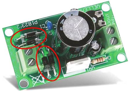
If you take a closer look at a power supply unit or the assembly of a power supply unit, you will very often discover the same component. This is the 1N4007 semiconductor diode, which is preferably used as a rectifier diode.
The reason why this diode is so popular with device manufacturers is its compact design and almost unbelievable dielectric strength. But these are not all the performance features that characterize this diode.
We would like to explain in more detail how the rectifier diode works and where it is used.
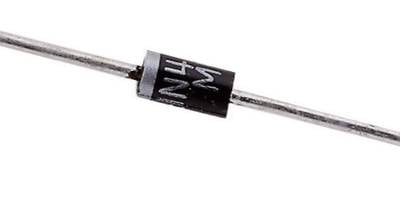
The 1N4007 rectifier diode is a silicon diode in a DO-41 or DO-204AL housing.
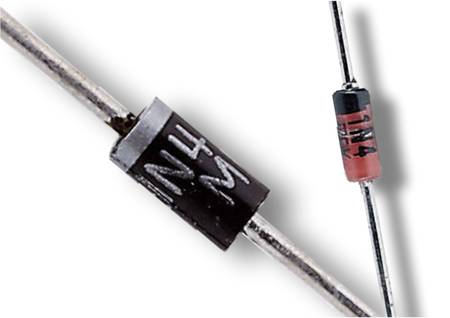
The cylindrical body of the diode has a diameter of approx. 2.6 mm and is 5.1 mm long. The diode has a connecting wire on the right and left which is approx. 2.8 cm long on each side and has a diameter of 0.77 mm. The cathode is marked with a bright ring to ensure that the diode is inserted correctly into the circuit.
At the heart of the diode is a semiconductor made of high-purity silicon that has been deliberately “contaminated” with foreign atoms. This process is also known as doping in technical jargon. Depending on which impurity atoms are used, either n-doped silicon or p-doped silicon is obtained. We have already described the exact structure of a pn junction with differently doped silicon lattice structures in more detail in our guide to the 1N4148 diode.
In our article on the 1N4148 diode, we also described the basic function of a semiconductor diode in great detail.
The 1N4007 diode also has a pn junction, in which the p-layer has defect electrons or holes and the n-layer has additional free electrons.
The pn-layer enables the 1N4007 diode to conduct current in one direction and block it in the opposite direction.
In contrast to diode 1N4148, however, diode 1N4007 has completely different electrical limit values. It can withstand significantly higher currents and higher voltages. For a better overview, we have compared the respective values of the two diodes.
Comparison table 1N4007 and 1N4148
| Diode type | Forward current | Blocking voltage | Forward voltage |
|---|---|---|---|
| 1N4007 | 1A | 1000V | 0.7V |
| 1N4148 | 0.15A | 75V | 0.7V |
Even if the continuous forward current and the reverse voltage are clearly different, the forward voltage of 0.7V is identical for both diode types. The high dielectric strength is precisely the reason why many circuit designers like to use the 1N4007 diode as a rectifier diode.
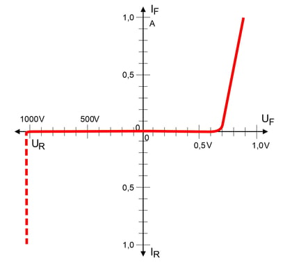
A characteristic curve can be used to graphically represent the interaction of different variables in a component. In the case of the 1N4007 diode, the relevant variables are current and voltage. Depending on the polarity of the voltage source or the applied voltage, the current that flows through the diode in the circuit changes.
If a diode is operated in the forward direction, the current will already start to flow at a forward voltage (UF) of approx. 0.7 V. However, the current must be limited so that the maximum permissible forward current is not exceeded.
No current will flow in the reverse direction as long as the permissible reverse voltage (UR) is not exceeded. However, if the breakdown voltage or Z voltage is exceeded in a prohibited manner, a very high current will suddenly flow through the 1N4007 diode, which will destroy the diode in a very short time.
In this case, the electrical circuit must be equipped with protective devices, such as fuses or electronic protective circuits, so that the impermissible current flow is stopped immediately and no major damage occurs.
In electronics, so-called Zener or Z diodes are also used, in which the breakdown behaviour when the Z voltage is reached is used to stabilize voltages. However, Z diodes can only withstand a limited breakdown current, which must not be exceeded under any circumstances. For this reason, the circuits in which Z diodes are used are designed accordingly.
Important:
The characteristic curve shifts slightly depending on the temperature of the semiconductor element. Specific details can be found in the data sheet or the technical description of the diode if required.
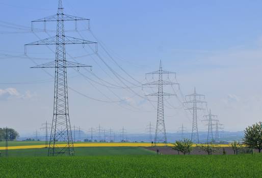
In order to keep line losses as low as possible when transmitting electricity, different voltages are used. While the voltage at a mains socket in the home is 230 V, the electrical energy on overhead lines is transmitted at up to 385,000 V. In order for the voltages to be transformed to the required value, AC voltage must be used. However, many devices do not work with alternating voltage.
It is true that televisions or computers, for example, are connected directly to the mains socket with AC voltage. However, the mains connection cable then leads directly into a power supply unit in the appliance, which generates various DC voltages of different levels from the AC voltage. Diodes are required as rectifiers to convert AC voltage into DC voltage.
AC voltage becomes DC voltage
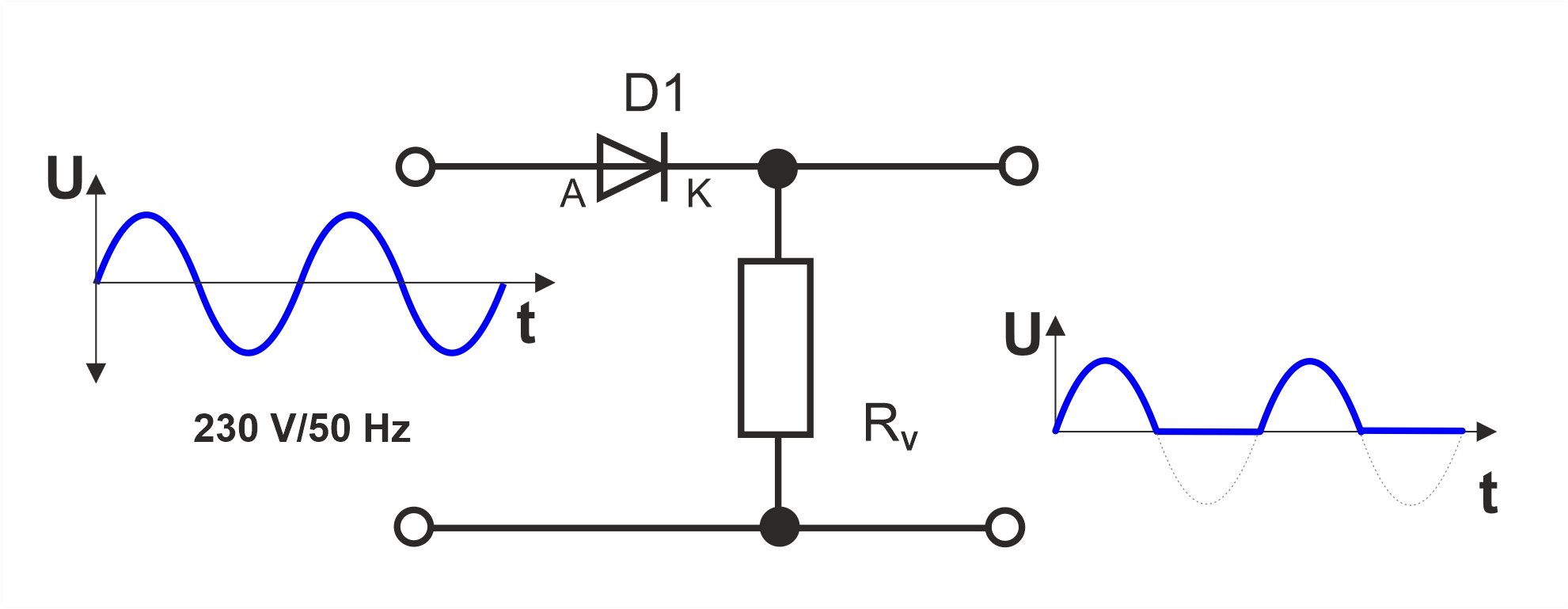
With AC mains voltage, the direction of the current changes 100 times per second. In this case, experts refer to a mains frequency of 50 Hz (Hertz). The curve is sinusoidal and there is an upper (positive) and a lower (negative) half-wave. To convert the AC voltage into a DC voltage, the lower half-wave must first be removed using a diode.
At the upper half-wave of the input voltage, the voltage at the anode (A) is higher than at the cathode (K). The diode (D1) acts as a conductor at this moment. The positive half-wave is transmitted to the load (RV).
With the negative half-wave of the input voltage, the voltage at the anode is lower than at the cathode and the diode acts as an insulator. No voltage can now be measured across the load.
As a diode only cuts off the negative part of the AC voltage, this half-wave rectification does not yet produce a true DC voltage. The positive half-waves with the gaps in between are rather a constantly fluctuating voltage with constant polarity.
A capacitor provides a remedy
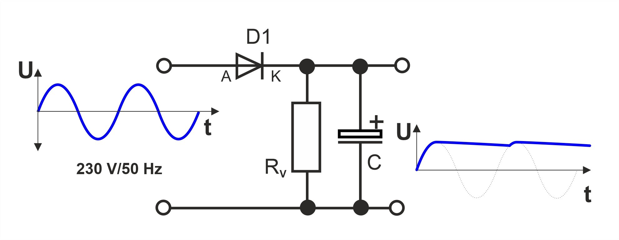
For this reason, a capacitor (C) is inserted into the circuit after the diode. The capacitor is charged by the positive half-waves and keeps the voltage between the half-waves at the same level as far as possible.
The capacitor must have a high capacitance so that the voltage between the half-waves does not drop too much. The voltage fluctuations between the half-waves are referred to as ripple.
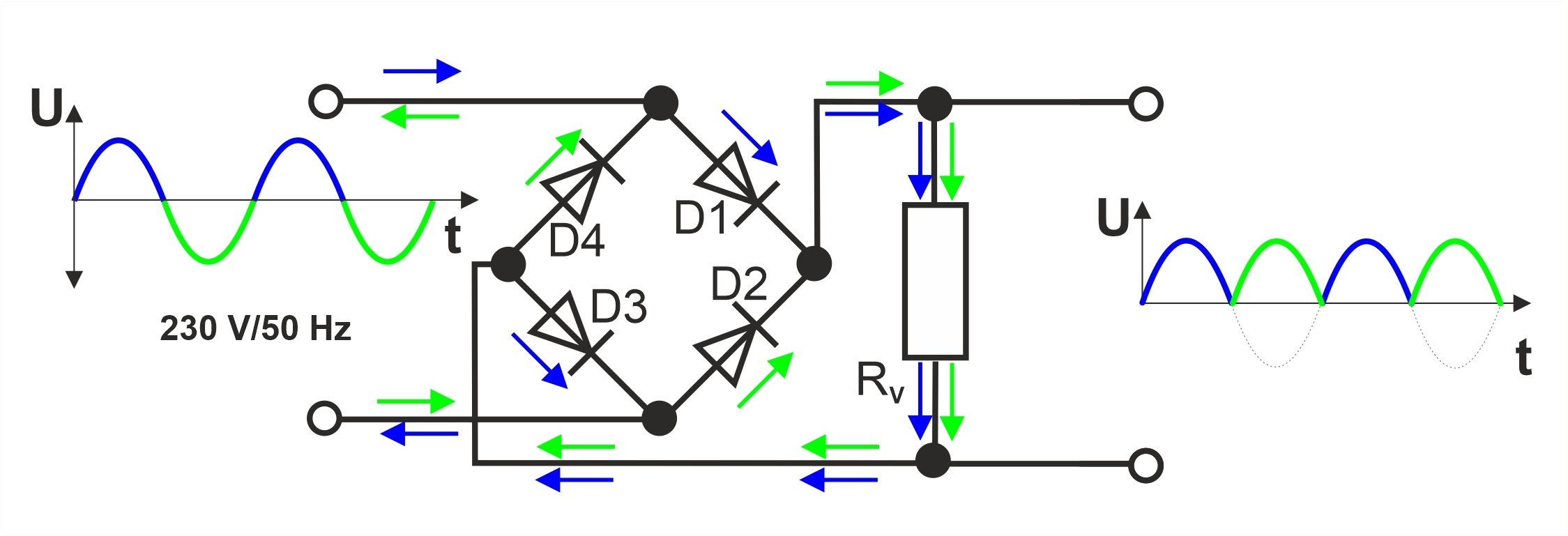
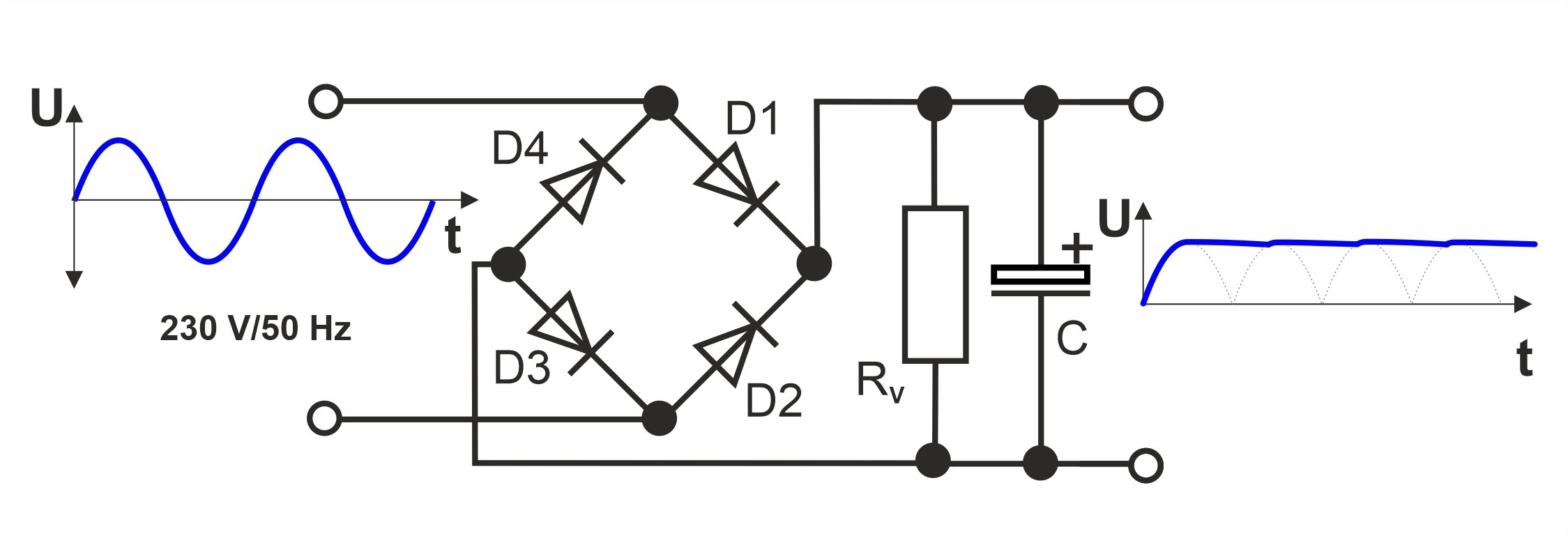
To ensure that the conversion from AC voltage to DC voltage works more efficiently, it makes sense not to simply cut off the lower half-wave. Instead, it should also be used. To do this, however, it is necessary to turn the negative half-wave into a positive half-wave. To fold the half-wave upwards, so to speak. This is exactly what a bridge rectifier with four diodes does.
At the positive half-wave at the input (shown in blue), diodes D1 and D3 conduct.
The diodes D2 and D4 are blocked, as at this moment there is a higher voltage at the cathodes than at the anodes.
With the negative half-wave (shown in green) it is exactly the opposite. Diodes D2 and D4 are now conducting and diodes D1 and D3 are blocked.
This circuit design reverses the polarity of the negative half-wave of the input voltage and turns it into a positive half-wave at the output. However, the output voltage is not yet a DC voltage. This is because the voltage constantly fluctuates between the peak value of the half-wave and 0 volts.
Capacitor for smoothing the voltage
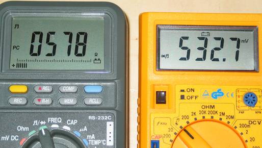
You can easily test a diode using a digital multimeter with a diode test function. The two connections of the diode are connected alternately to the two test leads of the measuring device.
Depending on the measuring device, however, the measurement results may be displayed differently.
If the measuring device is set to the measurement setting for testing diodes, either the forward resistance or the forward voltage can be displayed when testing the forward direction.
An intact diode has a forward resistance of approx. 400 - 800 ohms and a forward voltage of approx. 450 - 800 mV.
The reverse polarity of the diode can be checked by reversing the polarity. In this case, the resistance value is infinite and no forward voltage can be measured.
Our practical tip: Diode test
To avoid errors during the measurement, the diode should be completely removed from the circuit or at least one connection should be desoldered.
In the event of a fault, the diode may have a short circuit or be high-resistance. In the event of a short circuit, the resistance in the forward and reverse directions is very low and tends towards 0 ohms.
If the diode is highly resistive, the resistance in the forward direction is also extremely high. In both fault cases, no forward voltage can be measured.
Can I also use the 1N4007 diode if the maximum voltage to be blocked is well below 1000V?
Yes, that is possible. In this case, the diode still has reserves if a pulse peak occurs in the blocking direction in the event of a malfunction or fault. Alternatively, other diodes could also be used:
- The 1N4001 has a reverse voltage of 50V
- The 1N4002 has a reverse voltage of 100V
- The 1N4003 has a reverse voltage of 200V
- The 1N4004 has a reverse voltage of 400V
- The 1N4005 has a reverse voltage of 600V
- The 1N4006 has a reverse voltage of 800V
All the diodes listed can withstand a forward current of 1A.
If the forward current is slightly more than 1A, can a 1N4007 still be used?
No, this is not recommended because the maximum permissible current is 1A. In this case, it is better to use a 1N54XX series diode. These diodes can withstand a rated current or forward current of 3A and are therefore well above 1A. According to the data sheet, these semiconductor diodes are also available with different dielectric strengths:
- The 1N5400 has a reverse voltage of 50V
- The 1N5401 has a reverse voltage of 100V
- The 1N5402 has a reverse voltage of 200V
- The 1N5404 has a reverse voltage of 400V
- The 1N5406 has a reverse voltage of 600V
- The 1N5407 has a reverse voltage of 800V
- The 1N5408 has a reverse voltage of 1000V
