LM393 » Structure, function, and circuitry of the comparator IC clearly explained
This text is machine translated.
In technology, it is often necessary to compare two different voltages. So-called comparators are ideal for this task. Depending on which of the two voltages has the higher value, the comparator changes its switching state. This information is required by downstream electronics for certain control tasks.
Or, with the help of a fixed reference signal, you can check whether, for example, the voltage value of a sensor is present or not. Other possible applications for comparators include the generation of PWM signals, power supply regulations, trigger circuits, and applications in digital technology.
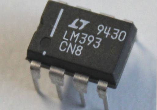
The LM393 integrated circuit contains two of these practical comparators, which we would like to present in more detail here.
The LM393 integrated circuit contains two independently operating comparators in one housing. As a result, the inputs and outputs of the comparators are also connected individually to the IC connections (pins 1–3 and 5–7). This means that six of the eight connections are already occupied.
The two remaining pins (pins 4 and 8) are used to supply power to the integrated circuit.
Attentive readers of our series of articles will immediately notice that the connection diagram is absolutely identical to that of the LM358 operational amplifier IC. And that is exactly correct. However, the LM393 does not consist of two integrated operational amplifiers, but rather two integrated comparators. This is why the LM393 IC is often referred to as a dual comparator. The integrated circuit is available both in the classic DIP housing for IC sockets and as a space-saving SMD component for direct mounting on the circuit board.
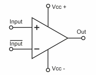
A comparator is essentially a device that compares two signals. Like an operational amplifier (OPV), a comparator has two inputs. One input is inverted and marked with a minus sign (-).
The other input is not inverted and is marked with a plus sign (+). Depending on which input has the higher voltage potential, the output of the comparator is switched. Therefore, a comparator can also be regarded as a 1-bit analog-to-digital converter.
In principle, this function can also be implemented with an operational amplifier. And in some cases, operational amplifiers are also used as comparators. However, there are subtle differences, which we will examine in more detail in a later chapter.
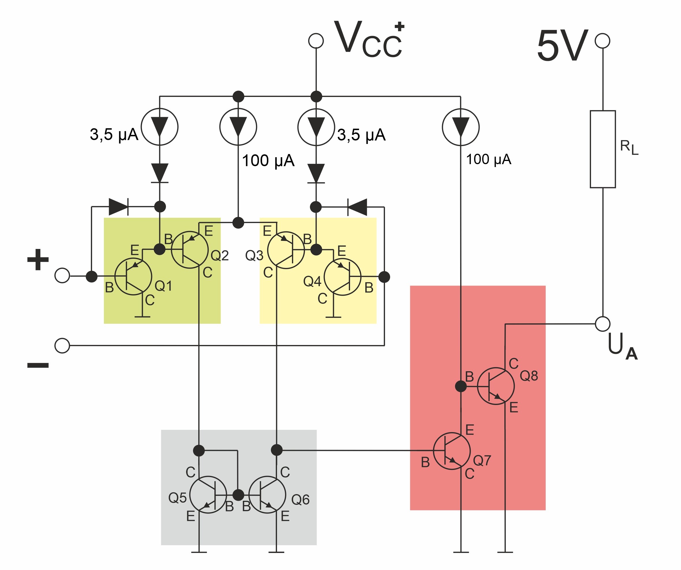
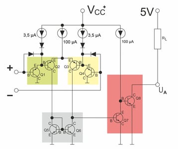
Transistors Q1 and Q2 (green) serve as the input stage for the non-inverted input. The input stage for the inverted input consists of transistors Q3 and Q4 (yellow). Transistors Q5 and Q6 (gray) function as current mirrors. Transistors Q7 and Q8 (red) represent the switching stage. The respective transistor stages are supplied via constant current sources.
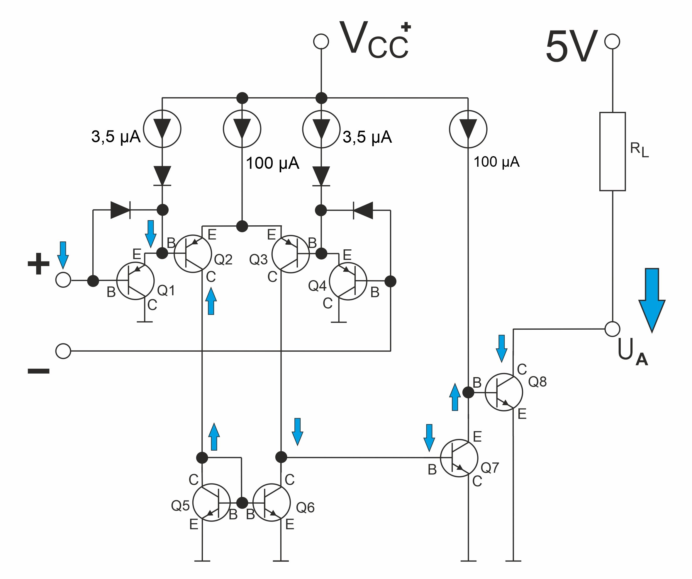
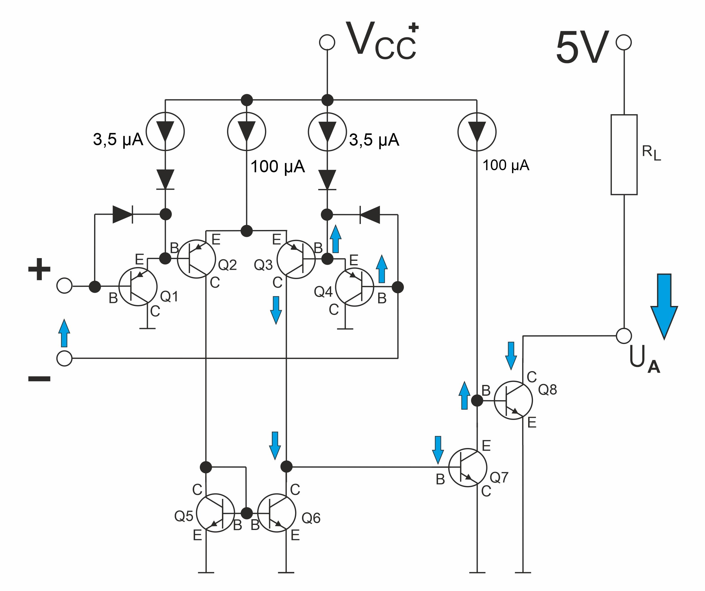
As soon as the input voltage at the non-inverted input (+) is higher than at the inverted input (-), the transistor (Q8) at the output of the comparator blocks. If the output is supplied with a voltage of 5 V via a resistor (RL), a “high” pulse can be tapped.
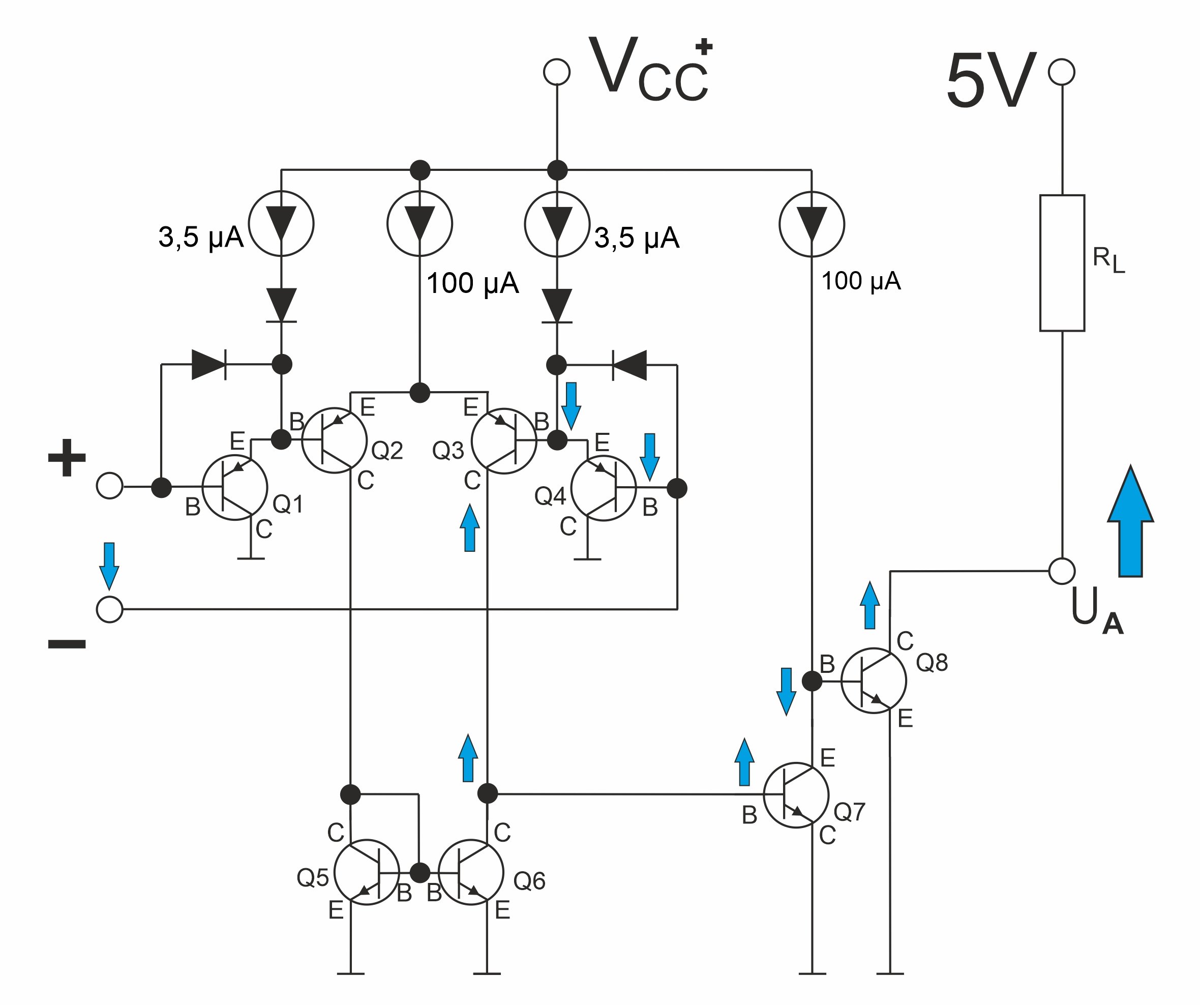
If the voltage at the non-inverted input is equal to or lower than that at the inverted input, the transistor at the output conducts. The output of the comparator is switched in the direction of the negative potential of the supply voltage. This allows a “low” pulse to be tapped.
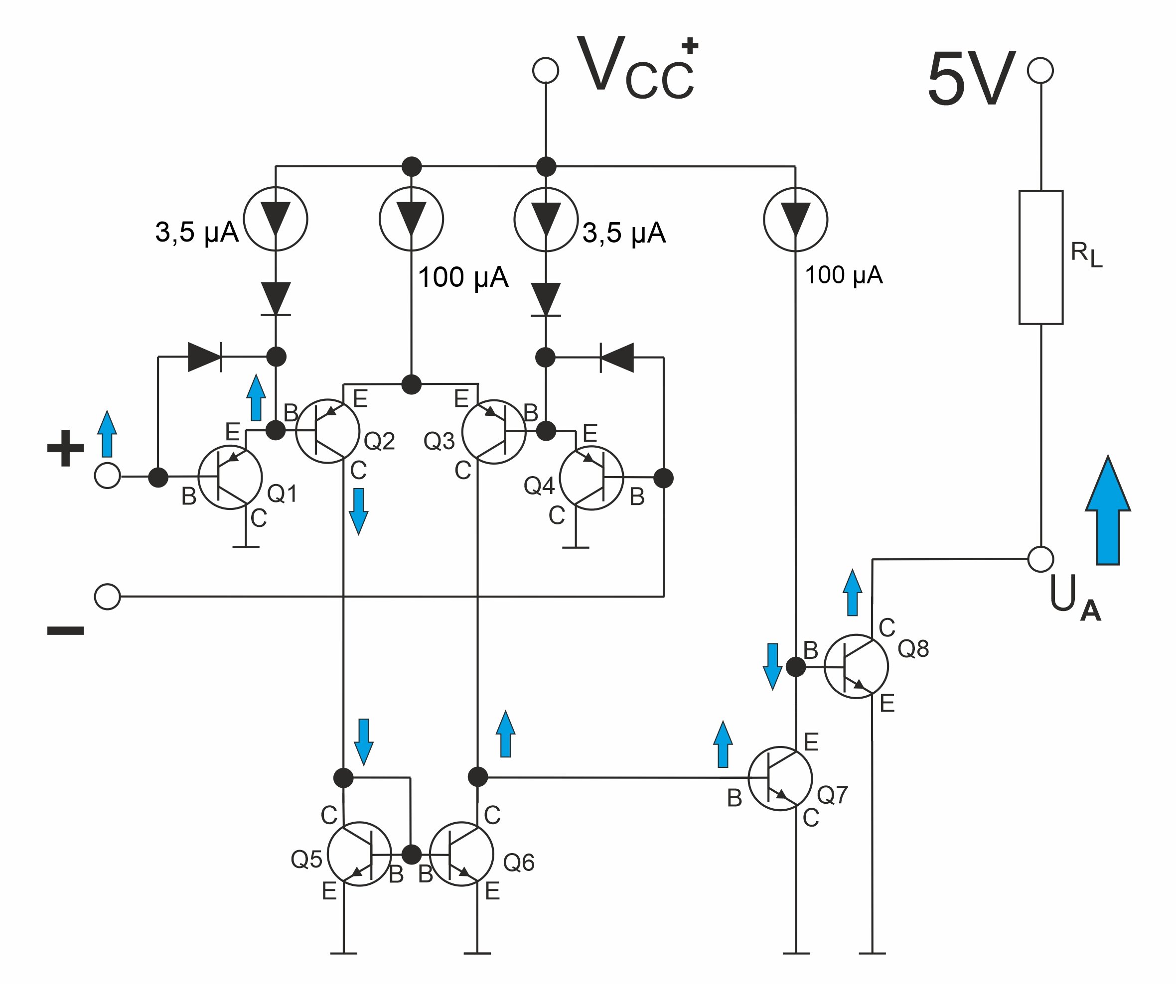
Whether the voltage changes at the inverted or non-inverted input is irrelevant for the switching function. The only important factor is the voltage difference between the two inputs. For better illustration, we have shown the various voltage changes (blue arrows) separately in the following switching examples.
Note:
If the voltage at both inputs changes simultaneously, i.e., at the same moment, in the same direction, and with the same magnitude, there will be no voltage change at the output of the comparator.
For a better overview, we have compared the schematic diagrams of an operational amplifier and a comparator.
If you look at the basic structure of an operational amplifier in the LM324, you will see a capacitor CC in the middle of the upper half. This capacitor is used for frequency compensation, which reduces the amplification of high frequencies. At the same time, stable operation of the operational amplifier is achieved and the tendency to oscillate or overshoot is suppressed.
However, this capacitor makes the operational amplifier “slow.” In addition, it takes longer for an operational amplifier to switch off again from the fully switched-on state (saturation). Therefore, OPVs should only be used as comparators if switching speed is not important. This can be the case in analog technology, for example.
Comparators do not have a capacitor for frequency compensation. They also do not have any internal amplification stages. As a result, comparators can also operate at higher frequencies. This also gives them a higher edge steepness at the output. Furthermore, comparators cannot be negatively fed back and used as amplifiers.
Power supply
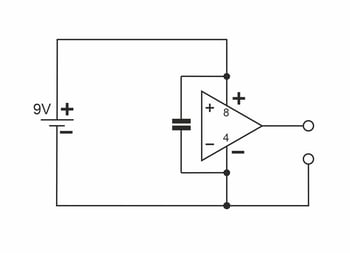
Like an operational amplifier, the LM393 comparator IC can be powered in two different ways. It is important that the supply voltages close to the IC are blocked against ground using low-inductance chip capacitors (approx. 100 nF).
Input circuitry
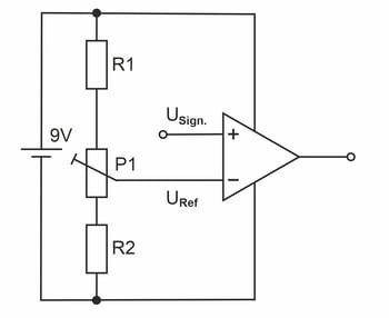
The two inputs can be wired individually. In most cases, the input signal (USign.) is applied to one input and a reference voltage (URef) to the other input.
The reference voltage essentially represents the threshold value at which the comparator switches. Depending on the circuit design, the reference voltage can be generated via voltage divider resistors (R1 and R2) and/or potentiometers (P1).
Alternatively, the reference input can also be connected to ground.
Output circuitry
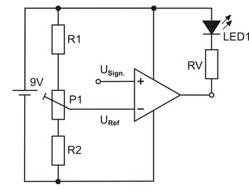
Unlike the LM358 operational amplifier, the output of the comparator in the LM393 does not serve as a voltage source or current source.
The comparator output is a so-called “open collector circuit.” This means that an external voltage must be applied to switch the comparator to ground or the negative potential of the supply voltage.
Important:
The current through the switching transistor Q8 in the comparator must not exceed 16 mA.
Further information and details on technical specifications can be found in the data sheet.
Electronic noise can cause interference signals at the inputs of the comparator. The interference signals or their voltage changes can cause the comparator to switch unintentionally under certain circumstances. This is prevented by using hysteresis in the circuit technology.
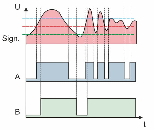
Without hysteresis, there is a threshold voltage (red line) that functions both as the switch-on voltage and as the output voltage. If the threshold voltage is exceeded by the signal voltage (Sign.) at the non-inverting input, the switching transistor in the comparator blocks. A high pulse can be measured at the output if the appropriate voltage is supplied.
If the voltage falls below the threshold voltage, the output is switched to low. Depending on the signal voltage at the input, this results in a binary code in the form of the output voltage A.
When hysteresis is used, the turn-on voltage and the turn-off voltage have different values. Only when the switch-on voltage (blue line) is exceeded and the switch-off voltage (green line) is undershot does the comparator operating with hysteresis trigger a switching operation.
The output signal B shows that voltage changes within the hysteresis limits do not trigger a switching operation.
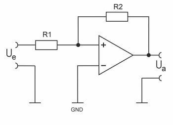
The different voltage values for switching on and off are generated by feedback or targeted positive feedback. To do this, part of the output signal is fed back to the non-inverted input of the comparator.
This causes the comparator to behave like a Schmitt trigger. The ratio of the two resistors R1 and R2 to each other defines the height of the two switching thresholds.
In practice, Schmitt triggers are also used for signal recovery, among other things. This is necessary when, for example, digital information has to be sent over long lines. The inductive and capacitive properties of lines distort the signals, and a clean square wave signal no longer arrives at the receiver. With a Schmitt trigger, the original signal shape can be easily restored.
Manufacturers provide further applications and circuit examples in their technical data sheets. This makes the LM393 comparator IC ideal for use in schools and vocational training. The various circuits can be easily replicated and comprehensively measured.
