ULN2003 Switching module » Structure and functionality clearly explained
Updated: September 7, 2022 | Reading time: 7 minutes
This text is machine translated.
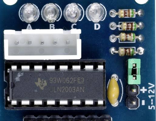
Switching modules, such as the 7-channel ULN2003 module, are very commonly used in electronics. The reason why circuit developers like to use the ULN2003 switching module is its versatility. Whether it's a relay card, stepper motor, or a simple level indicator, these circuit tasks can be realized very easily with the ULN2003 switching module as a driver. We explain how the integrated circuit works, how to connect it correctly, and what to consider when using it.
The ULN2003 switching module is an integrated circuit or IC (integrated circuit). An integrated circuit integrates a large number of individual semiconductors, such as transistors and diodes, into a single housing. The major advantage of this technology is the enormous space savings and minimal effort required for the external wiring of an IC.
With the help of the integrated transistors, a weak control signal is amplified so that, in addition to powerful light-emitting diodes, relays, small motors (DC), or stepper motors can also be operated. Because in most cases several control signals need to be amplified, the ULN2003 switching module has seven inputs and seven outputs. This makes it easy to control a stepper motor as desired using an Arduino board or Raspberry Pi board.
The two main tasks of the ULN2003 are amplification and switching. This is achieved with the help of bipolar NPN transistors. In our guide to the BC 547 transistor, we have clearly explained the basic function and amplification properties of a transistor.
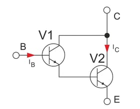
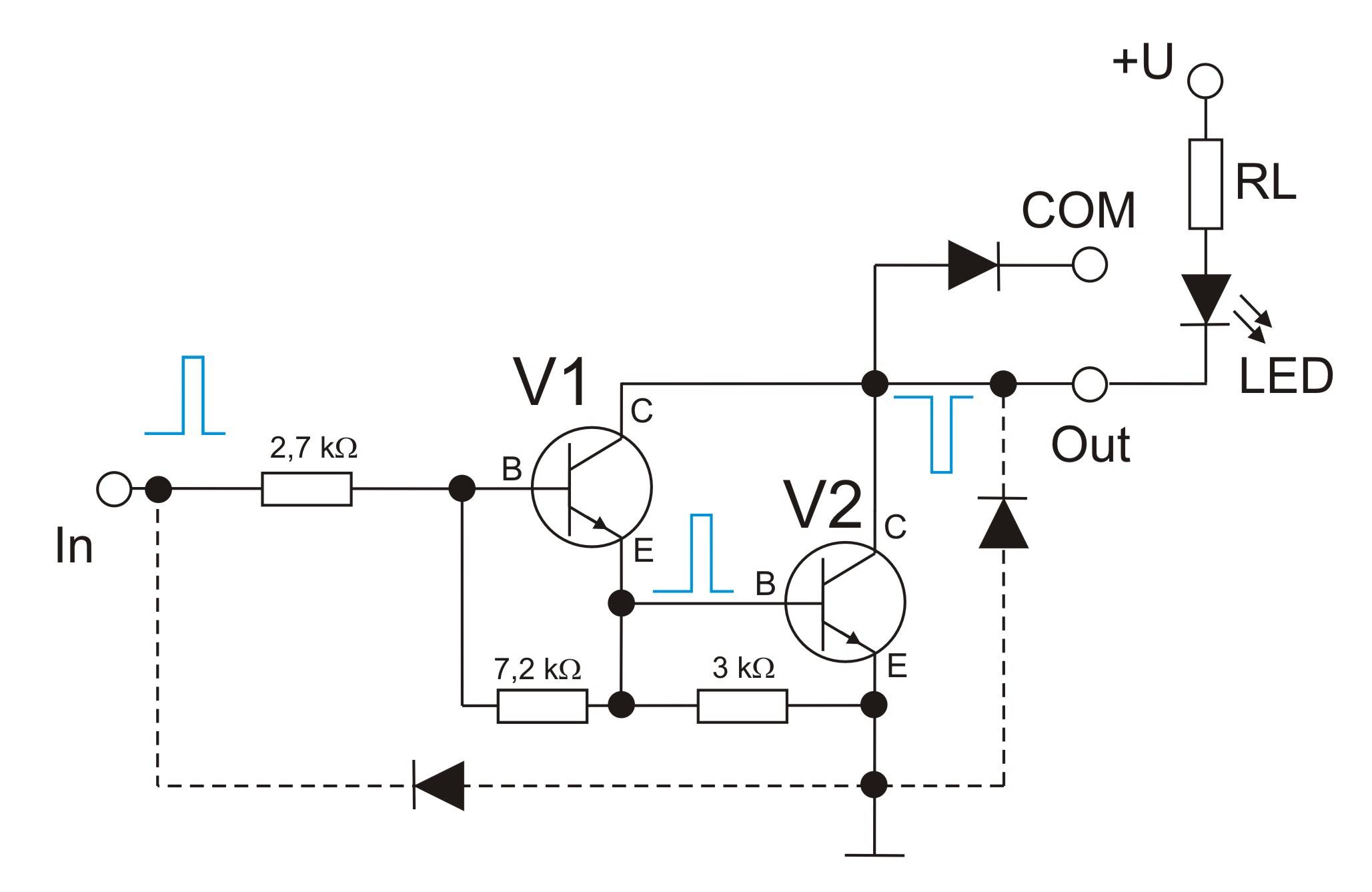
If two NPN transistors (V1 and V2) are directly coupled together, the result is a Darlington circuit. If both transistors are housed in a common casing, experts refer to this as a Darlington transistor.
Basic function of a Darlington transistor arrangement
The major advantage of the Darlington transistor arrangement is its extremely high current gain. In practice, a minimal base current (IB) at transistor V1 is sufficient for transistor V2 to switch on and the connection between the collector (C) and emitter (E) to become low-impedance. This allows a high collector current (IC) to flow.
For this to happen, the base-emitter voltage must be approximately 1.4 V. With a single NPN transistor, a base-emitter voltage of 0.7 V is sufficient. In addition, depending on the current, the collector-emitter voltage can still be up to 2 V when the transistor is switched on.
Pin assignment of the ULN2003 switching module
A total of seven of these Darlington switching stages are integrated in the ULN2003 switching module. This is why the ULN2003 integrated circuit is also referred to as a Darlington transistor array. In addition to transistor arrays, resistor arrays and diode arrays are also used in electronics to save space in circuit design.
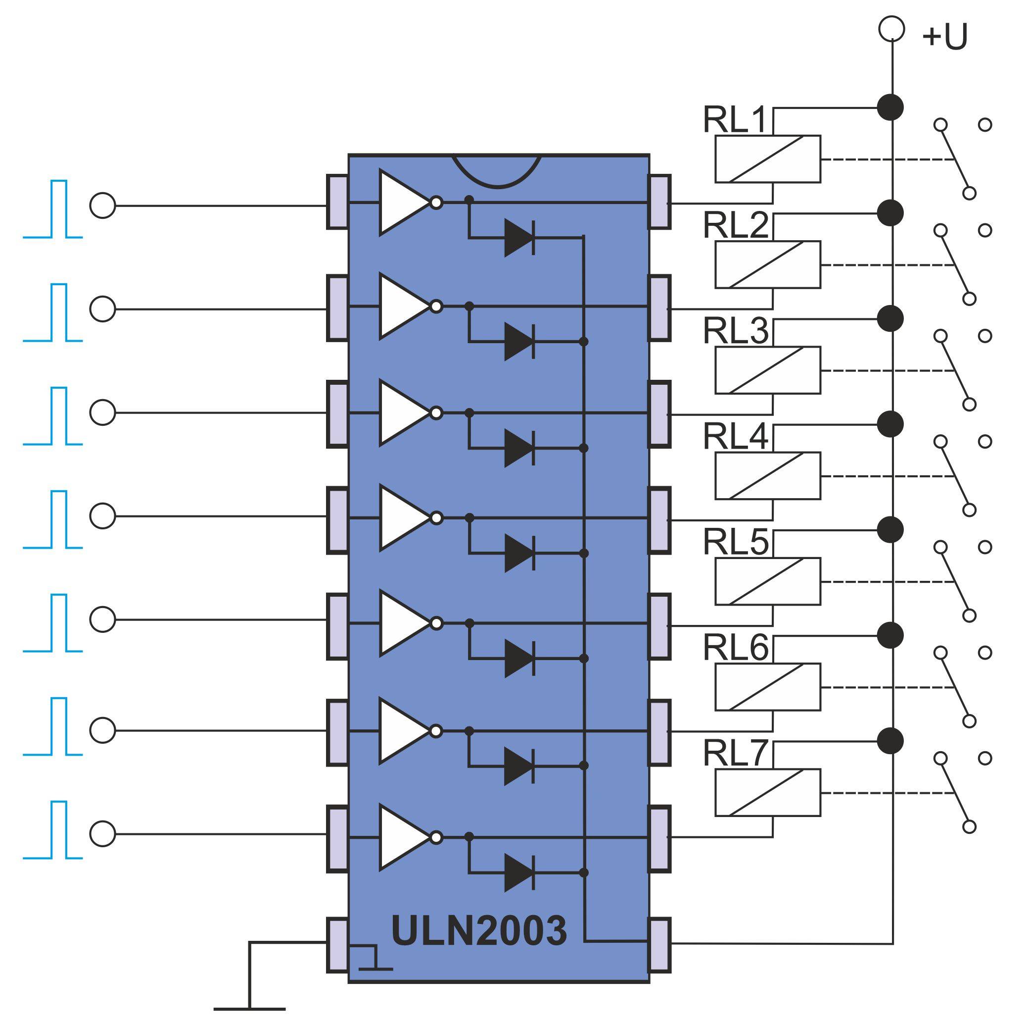
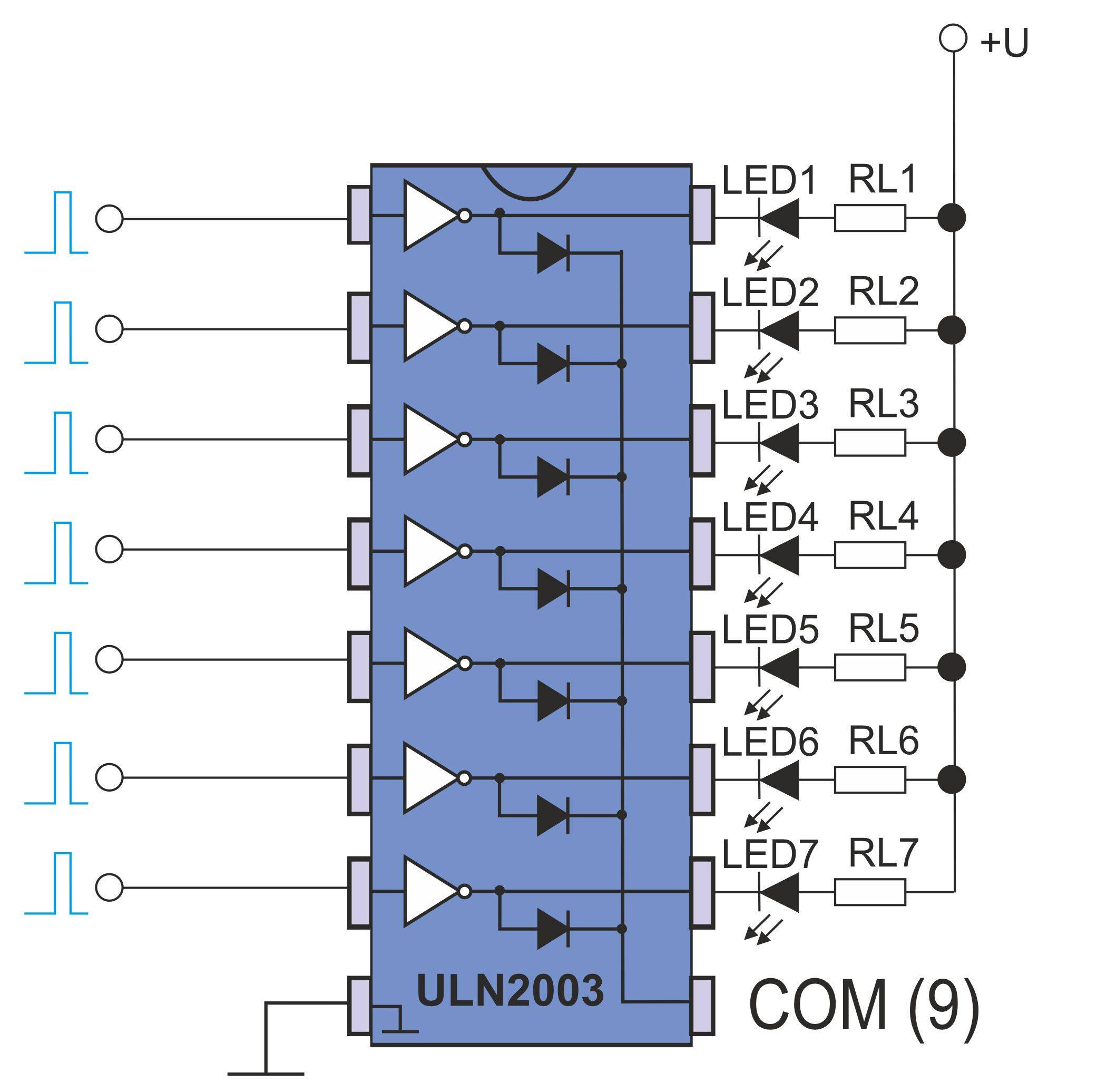
For simplicity, the switching stages or current amplifiers are simply drawn as small triangles.
Since a voltage increase at the input causes a voltage decrease at the output, the signal is effectively reversed or inverted. This signal reversal is represented by the small circle on the right side of the triangle.
To ensure that the component is used correctly in the circuit, it has a semicircular marking on one narrow side. The connection to the left of this is connection pin 1. Some manufacturers mark pin 1 with an additional dot. The remaining numbering runs counterclockwise when viewed from above.
The inputs of the seven switching stages are located on the left side of the IC and occupy connection pins 1 to 7. The outputs of the seven switching stages are located opposite the inputs on the right side of the IC and occupy pins 10 to 16.
In addition, each output is equipped with a free-wheeling diode so that inductive loads such as relays or motors can also be switched without damage. We have explained the exact function of a free-wheeling diode in more detail in our guide to the 1N4148 diode. All cathodes of the seven free-wheeling diodes are connected internally and are routed to the outside at PIN 9 (COM). Connection pin 8 serves as the ground connection (GND = Ground).
Different versions
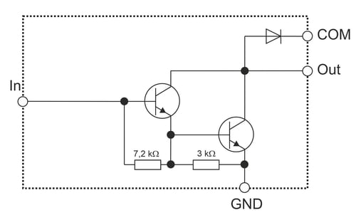
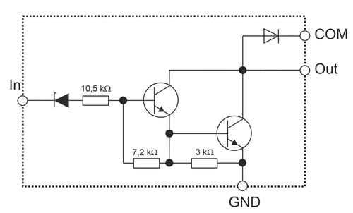
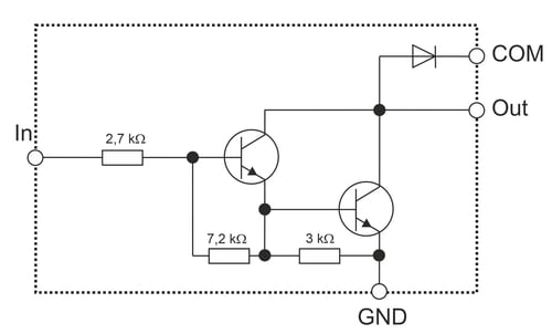
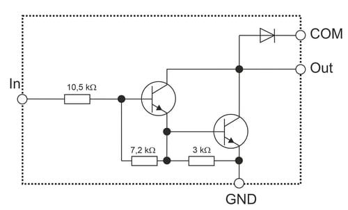
In addition to the version in the DIP housing already shown (ULN2003A), the switching module is also available as an SMD component (ULN2003D1). Furthermore, the ULN2003 switching module belongs to a family of ULN switching or driver modules, all of which have the same basic function but are designed for different circuit environments. As a result, additional diodes and resistors are integrated into some of the Darlington stages in order to be able to process the different input voltages.
The individual versions differ only in terms of the different wiring of the input (In).
We have already explained the exact function of a Darlington switching stage in a switching module in detail in our guide to the ULN2803.
The ULN2803 switching module is almost identical to the ULN2003, but has a total of eight switching stages instead of seven.
As a result, the ULN2803 IC also has two more connection pins than the ULN2003.
In addition to the connections for the seven inputs and outputs, the switching module also has a connection (pin 8) for ground (GND). This connection is the common ground connection for the seven inputs and the seven switching stages. An Arduino, for example, could be used to control the inputs.
Pin 9 (COM) is the common connection for the seven free-wheeling diodes and is only required when connecting inductive loads such as relays or motors. In this case, pin 9 is connected to the supply voltage of the connected consumers. If only powerful LEDs are connected, e.g. for a light display, pin 9 remains unassigned.
For a better overview, we have illustrated the two connection variants again.
Important:
As with any other electronic component, care must be taken when using the switching module to ensure that the maximum permissible limits for current and voltage are not exceeded.
If the operating voltage for the connected loads is higher than the operating voltage of the control electronics, only the ground potentials of the two voltages need to be connected to each other. This is the case, for example, if one or more 12V relays or a 12V motor are to be switched with a 5V control signal.
ULN 2003 characteristic curves
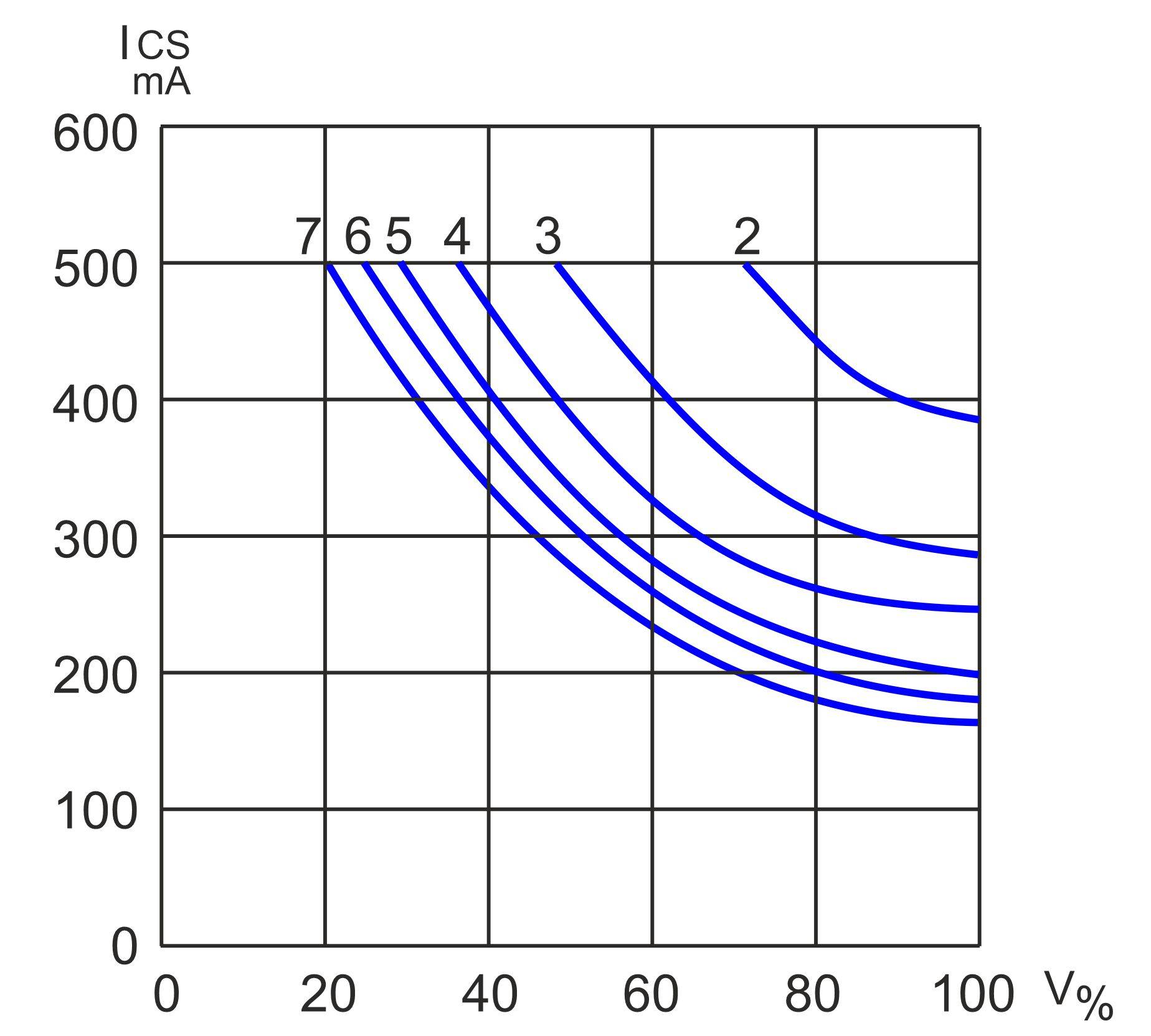
According to the data sheet, the Darlington transistors in the ULN2003 can switch voltages up to 50 V and currents up to 500 mA. The outputs can also withstand currents up to 600 mA for short periods. However, not all outputs can be loaded with such high values simultaneously and continuously. Otherwise, the power dissipation for the switching module would be too high. Therefore, the maximum possible current is reduced when several outputs are operated simultaneously.
In addition, the duty cycle also plays an important role. The shorter the switch-on pulse and the longer the pause between pulses, the higher the current value can be. With a ratio of 1:5 or 20%, the maximum current can still be used for all seven switching stages. As the percentage value increases, the usable current or the number of simultaneously used switching stages that can be loaded with 500 mA decreases.
If all 7 transistor stages are permanently switched through (duty cycle 100%), each stage may be loaded with a maximum of 160 mA. The technical data includes diagrams that show exactly how high the load capacity of the individual switching stages is under different conditions.
Simple circuit designs using the ULN2003 switching module are particularly suitable for schools or training purposes. One example would be a simple water level sensor for rainwater cisterns, which can be built around the switching module with just a few external components. Since the power supply is provided by a 9 V block battery, this circuit is ideal for practical teaching.
The circuit can be built either on a breadboard or on a plug-in board. For a permanent setup and to acquire soldering skills, assembly on a circuit board is preferable. We have clearly illustrated the correct use of a soldering iron.
If the circuit is only intended for experimentation, a solderless setup on a breadboard or plug-in board is suitable.
Circuit description of the cistern level indicator
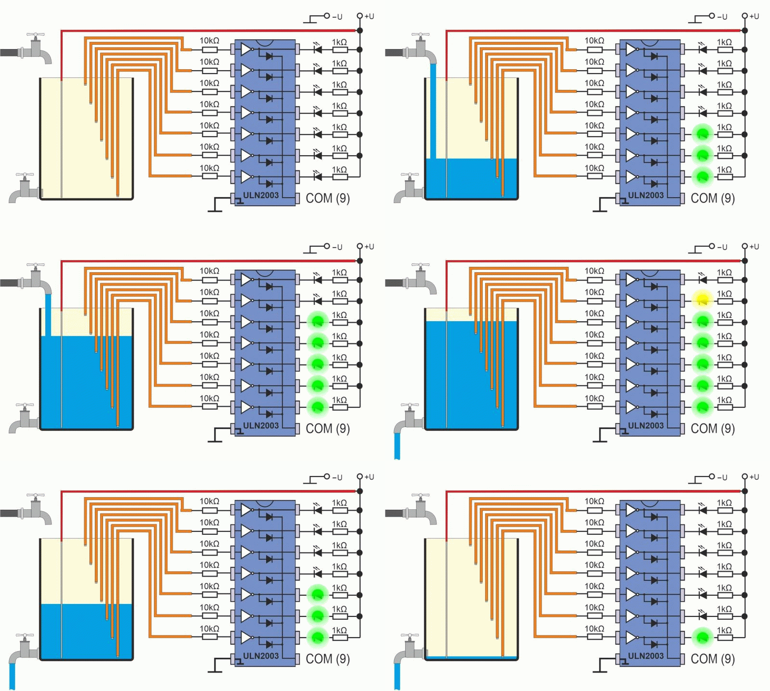
The structure of the LED display of the water level indicator or fill level indicator corresponds exactly to the connection diagram for ohmic loads already explained. Depending on requirements, standard LEDs with different colors can be used to make the display more informative. At an operating voltage (VCC) of 9–12 V, LED series resistors with a value of approx. 1 kΩ provide sufficient brightness without glare. However, if the full luminosity of the LEDs is desired, the series resistors for the respective light-emitting diodes must be calculated separately.
Insulated wires are used on the input side of the IC, with the stripped cable end serving as a sensor for the water. The wires are each connected to the inputs of the IC via a 10 kΩ resistor. Another wire (electrode) also feeds the positive potential (+U) of the supply voltage into the water tank.
When the supply voltage is connected and the water tank is empty, the LEDs do not light up.
However, as soon as tap water or rainwater is poured into the tank, the salts dissolved in the water act as electrical conductors.
This causes a minimal current to flow from the positive electrode through the water to the sensors and on to the ULN2003A IC.
This very low current is sufficient to activate the Darlington switching stage in the ULN2003, causing the LED at the output to light up.
If the input sensors are mechanically installed at different heights, the fill level can be accurately displayed using the LEDs. If necessary, the circuit can also be constructed with two or three ICs. This provides 14 or 21 different measuring points, which enable a very fine subdivision of the water level in the rainwater cistern.
Further opportunities for experimentation
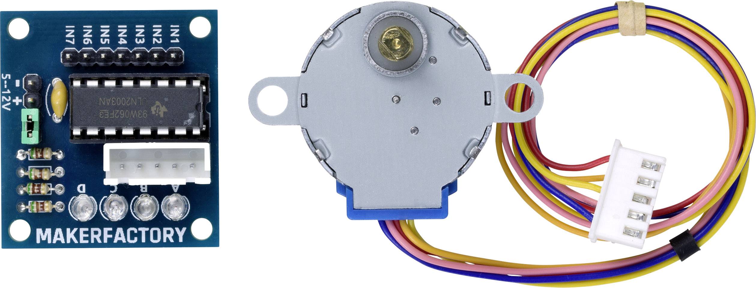
Of course, more complex circuit designs are also possible. For example, the ULN2003A switching module could be used as a motor driver and combined with a 5V stepper motor or DC motor. The switching module is then controlled using, for example, an Arduino single-board computer. In this context, a suitable program can also be created for the Arduino to control the stepper motor individually.
From a technical standpoint, there are virtually no limits to experimenting and tinkering with the ULN2003.
