Electromagnetic compatibility (EMC) of electronic devices
Published: 09.08.2023 | Reading Time: 6 minutes
This text is machine translated.
Today it is unimaginable what was still quite common in the 1970s. Back then, when the black and white tube TV was switched on, interference-free reception was not always guaranteed despite the antenna being intact.
If the children were playing with the electric car racing track in the next room and the sparks on the sliding contacts of the racing cars were spraying, picture and sound interference was virtually pre-programmed. In those days, a vacuum cleaner or hairdryer switched on at the same time could also very quickly ruin the viewing experience.
Fortunately, thanks to electromagnetic compatibility, these unpleasant experiences are now a thing of the past. We will be happy to explain to you what EMC or electromagnetic compatibility is all about and why it is so important.
In order to better understand electromagnetic compatibility, let's revisit the example mentioned at the beginning with the racetrack and the television. The flying sparks during current transmission at the sliding contacts generate very high voltage peaks. These can spread back into the power grid via the conductors in the rails and the transformer. At the same time, the current conductors in the rails and the connecting cables of the transformer act like antennas, so that the high-frequency components of the voltage peaks are emitted as electromagnetic radio waves. As a result, the interference with the television was mostly via the power grid and partly via direct radio radiation.
This changed at the beginning of the 1980s, when the Association of German Electrical Engineers drew up new regulations regarding interference emission and immunity of electrical equipment. Even then, it was recognized that the problem had to be tackled from two sides.
On the one hand, devices and systems must not actively emit any interference. On the other hand, they must be built in such a way that any electromagnetic interference from other devices is effectively blocked.
Electromagnetic compatibility is now taken into account during product development and tested before series production.
Thanks to the minimal interference emission and maximum interference immunity, the simultaneous interference-free operation of many devices and systems is possible without any problems. Even in the smallest of spaces and in the same electromagnetic environment. The various requirements of the DIN VDE regulations on EMC have since been incorporated into the European standards (EN standards) and international standards (IEC).
The three letters EMI are often used in connection with EMC. The abbreviation EMI stands for Electromagnetic Interference, among other things. Interference is the superposition of waves, whereby the waves can amplify or cancel each other out depending on their phase position. Electromagnetic interference describes an operational disturbance caused by the electromagnetic field of an external source in an electronic device. Natural sources of interference include, for example, solar radiation or electrostatic discharges (lightning). Man-made sources include power lines, electrical devices and radio transmitters.
One of the reasons why technical devices, electronic products or systems generate more or less EMI interference is that electronic components build up electrostatic or electromagnetic fields as soon as voltage is applied or current flows. Without this effect, capacitors, transformers or relays, for example, would not be able to function.
However, there are also constellations in technology where the field effect has an extremely negative impact. This is the case in a switching power supply, for example, where high voltages are switched on and off in a rapid rhythm.
The resulting electromagnetic interference must be prevented as far as possible during the development of the power supply unit by taking suitable measures.
Note:
In connection with electromagnetic compatibility and the term EMI, the abbreviation RFI is often used in electronics. The three letters RFI are derived from the term Radiofrequency Interference and primarily refer to high-frequency interference. EMI and RFI are the two main factors that must be taken into account when assessing electromagnetic compatibility.
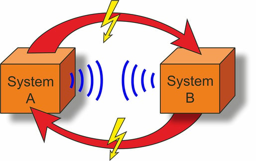
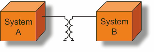
In order for two systems to interact with each other, there must be a connection or transmission. Experts then speak of a coupling that exists between the interference source (transmitter) and the interference sink (receiver). Depending on how the systems are mechanically constructed, the coupling can take place in different ways:
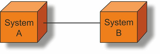
Conductive coupling
With conductive coupling, the individual systems or assemblies are directly connected to each other with a wire or cable. However, the countless conductor tracks on a circuit board or the parts of a metal housing can also cause an internal conductive coupling between the different assemblies of a device.
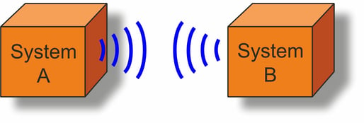
Radiation coupling
In the case of radiation coupling, interference is caused by the air. This is because every conductor track and every wire in a device can behave like an antenna under certain circumstances. Depending on the area of the device in which they are located, electromagnetic interference can either be emitted or received.
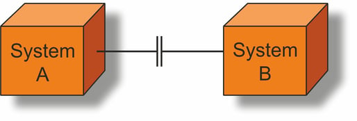
Capacitive coupling
Capacitive coupling occurs when there is a different electric field between two neighboring conductors. This can be cables running in parallel or conductors placed next to each other. In this case, these parts behave like a capacitor. The smaller the distance, the higher the capacitance.
Inductive coupling
In addition to capacitive coupling, inductive coupling can also occur with parallel conductors. In this case, it is not the electrostatic field but the electromagnetic field that is decisive. The magnetic field of an electrical conductor can induce an electrical interference voltage in the second electrical conductor.
Note:
Capacitive coupling is predominantly voltage-dependent, whereas inductive coupling is primarily current-dependent. The higher the respective values, the stronger the coupling effect.
The reduction or suppression of EMI and RFI interference is a very complex issue that must be taken into account during the development of a product. Otherwise, there is a risk that the product will fail the final EMC test and a cost-intensive redesign of the finished device will be necessary. In this case, it is then necessary to check exactly which interference faults occur at which points and how this can be prevented.
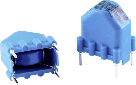
In order to meet the requirements of the EMC Directive or the applicable standard, filters or shields are preferably used. These technical components are available in a wide variety of shapes and designs. Individual components or cables, larger assemblies or even complete devices can be shielded with electrically conductive materials such as shielding plates or special housings.
In some cases, however, special components for EMI suppression, such as ferrite cores or suppression chokes, are also integrated during circuit development.
For appliances that have a mains connection cable, so-called interference suppression filters are used. These mains filters are located directly at the input of the power line and contain specially tuned coils and capacitors. This prevents the interference generated in the appliance from reaching the outside via the power cable. At the same time, the mains filters ensure that any interference can enter the appliance via the mains connection cable.
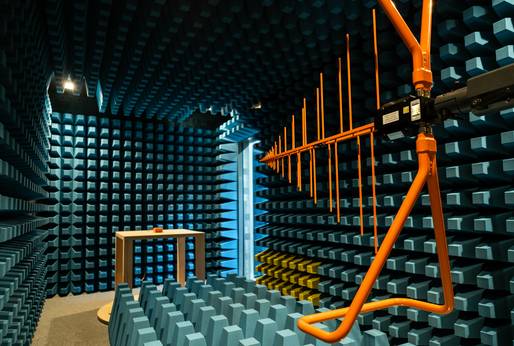
Performing an EMC measurement depends on many factors and requirements. Apart from large technical installations or systems that have to be tested on site, most EMC measurements are carried out in an anechoic chamber of an EMC laboratory.
Thanks to the hermetic metal cladding, radio signals and radio interference cannot penetrate inside or reach the outside. In addition, special absorbers in the interior ensure that the ceiling and walls do not reflect any signals and thus falsify the measurement results.
In accordance with the requirements of EMC standards and EU directives, product-specific EMC tests for interference immunity and emitted interference are then carried out.
In accordance with the standards EN IEC 61000-6-1:2019 and EN IEC 61000-6-2:2019, a distinction is made between two classes for high-frequency devices that unintentionally emit high-frequency fields:
EMC class A for use in industrial environments
EMC class B for use in or in the immediate vicinity of residential, commercial and industrial areas
The EMC Machinery Directive (2003/42/EC) applies to machines with electrical or electronic components that cause electromagnetic emissions or are exposed to interference radiation in the form of electromagnetic fields. The measurement methods and test setups used are always tailored to the device to be tested and can vary greatly. Irrespective of this, a passed EMC test can serve as the basis for CE marking if required.
As the EU Directive 2014/30/EU (EMC Directive) on compliance with EMC requirements does not have the character of a law, the EU member states had to convert the EMC Directive into a national law. In Germany, the Electromagnetic Compatibility Act (EMVG) was therefore passed in 2016. This law is binding for manufacturers, distributors and dealers. Like the EMC Directive, the EMC Act does not contain any technical specifications regarding the permissible limit values. These are laid down in the various standards that must be applied.
Even if it is not currently mandatory, EMC tests should definitely be carried out prior to market launch. This is because if a non-EMC-compliant or EMC-compliant product emits an excessively strong electromagnetic interference signal, the authorities will demand that the defect be rectified quickly. This then affects the devices on the market as well as the entire stock. If the request is not complied with immediately, there is a risk of high fines, product recalls and sales bans. If there is an immediate danger to life and limb, the affected appliances will even be destroyed.

