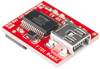
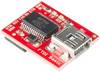
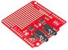
This is the latest revision of our FTDI Basic. We now use a 6-pin SMD plug on the bottom, was smaller and more compact. The functionality has remained the same.
This is a simple breakout board for the FTDI FT232RL USB to serial IC. The layout of this board is the same as the FTDI cable to work with official Arduino and cloned 3.3V Arduino boards. It can also be used for general series applications. The main difference to this board is that it releases the DTR pin as opposed to the RTS pin of the FTDI cable. The DTR pin allows an Arduino destination to reset automatically when downloading a new sketch. This is a really nice feature that allows you to download a sketch without pressing the reset button. This board automatically resets each Arduino board that has the reset pin on a 6-pin connector.
The pins marked BLK and GRN correspond to the colored wires on the FTDI cable. The black wire on the FTDI cable is GND, green is DTR. Use these BLK and GRN pins to align the FTDI baseboard with your Arduino target.
There are advantages and disadvantages to the FTDI cable compared to the FTDI basic device. This board has TX and RX LEDs that allow you to see the serial traffic on the LEDs to verify that the board is functioning, but this board requires a mini-B cable. The FTDI cable is well protected against weather influences, but large and cannot be easily integrated into a project. The FTDI Basic uses DTR to trigger a hardware reset where the FTDI cable uses the RTS signal.
This board is designed to reduce the cost of Arduino development and improve user experience (the automatic reset of the feature rocks!). Our Arduino Pro and LilyPad boards use this type of connector.
This text is machine translated.