Calculate LED series resistor » Determine the correct series resistor for each LED
This text is machine translated.
Published: 07.09.2022 | Reading time: 9 minutes
LEDs have proven their worth as visual indicators for decades. In a wide variety of devices, they indicate the correct power supply, the current operating status or even different switching states. This is not surprising, as LEDs require very little power and therefore do not generate excessive waste heat. LEDs as display elements are also extremely durable, robust and available for little money. This is why they are so popular with appliance manufacturers.
But LEDs are not only used in professional appliance development. Electronics fans in the hobby sector also swear by LEDs when electrical signals or voltages need to be displayed visually. But how should LEDs be connected and operated correctly so that they light up for a long time and don't burn out immediately? We will be happy to explain what you need to bear in mind.
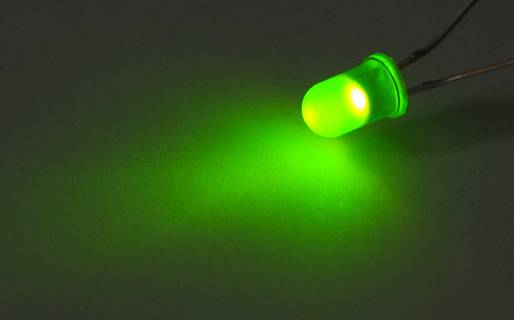
To answer this question in concrete terms, we first need to take a closer look at an LED. In order for an LED to light up, it is operated in the forward direction.
We have described this functional principle in detail in our guide to the 1N4148 diode. An LED only starts to light up when the voltage difference between the anode and cathode (LED forward voltage) is high enough.
How high the forward voltage is for standard LEDs depends primarily on the wavelength and therefore the color of the emitted light.
Overview of forward voltages for different LED colors
| Color | Forward voltage |
|---|---|
| Infrared | 1.2 V |
| Red | 1.8 V |
| Yellow | 2.0 V |
| Green | 2.2 V |
| Color | Forward voltage |
|---|---|
| Green (ultra bright) | 3.3 V |
| Blue | 3.6 V |
| White | 3.6 V |
| Ultraviolet | 4.0 V |
The values given in the tables are for guidance only. The actual values of the light-emitting diodes used may vary and must be taken from the technical data sheets if necessary.
Important!
The forward voltage must not be regarded as the operating voltage for the LED. Rather, the forward voltage represents a voltage value regulated by the LED at which it reaches its operating point and lights up. Consequently, the voltage that can be measured via an illuminated LED will remain approximately the same, even if the series resistor is changed from 560 ohms to 470 ohms, for example. Only the current and therefore the luminosity will increase due to the smaller series resistor.
Limit voltage and current for the LED
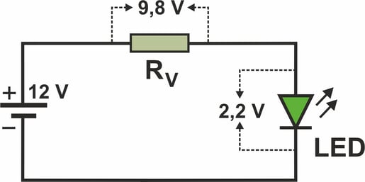
The reason why an LED requires a series resistor is that the forward voltage of an LED is relatively low. In many circuits and devices, the available voltages that are to be visually indicated by an LED are often much higher. This occurs, for example, when the 12 V supply voltage of an easy-to-install cistern level indicator is to be displayed with a green LED.
As the diode has a forward voltage of only 2.2 V, the excessive voltage must be reduced with a series resistor (Rv). So that the voltage to be destroyed can drop across the resistor, it must be connected in series with the LED as a voltage divider.
The series resistor must also be dimensioned so that the exact differential voltage of 9.8 V (12 V - 2.2 V) can drop across it. If a blue LED is to be used instead of a green LED, a voltage of 8.4 V (12 V - 3.6 V) should drop across the series resistor.
The second important reason why a series resistor should be used is to limit the current. This is because an LED as a semiconductor does not behave like an ohmic resistor with a constant value. As soon as the applied voltage is high enough and the LED starts to light up, the internal resistance of the LED drops drastically. This would cause more and more current to flow through the LED. This continues until the LED is ultimately destroyed. The series resistor prevents this by limiting the current through the diode to the permissible value. This is why LEDs should never be operated without a series resistor. Even if the supply voltage is only slightly higher than the forward voltage.
Of course, we know that there are some more or less practical LED resistor calculators on the World Wide Web. After entering the LED voltage and the LED current, these tools automatically calculate the correct resistance for a specific operating voltage. However, as the Internet is not always available everywhere, it makes sense to be able to calculate the required resistance values yourself. Especially as the calculation is quite simple and easy to understand.
Calculate the resistance value of the series resistor
The calculation of the required resistance value is quite simple and is based on Ohm's law. However, in order to apply the formula R = U : I, the current required by the LED must be known. Just like the forward voltage, the forward current (If) is also specified in the technical data of the LEDs.
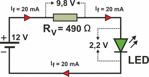
Let us assume that the green LED mentioned above with a forward voltage of 2.2 V requires a continuous current of 20 mA in the forward direction.
The series resistor can now be easily calculated using these values. This is because the current of 20 mA, which flows through the diode with the required series connection, must of course also flow through the resistor.
According to Ohm's law, this results in the following calculated resistance value: R = 9.8 V : 0.02 A = 490 Ω.
Important:
To ensure that the correct value in ohms is determined during the calculation, voltage and current should always be calculated in the same units, i.e. volts and amperes. In this case, 0.02 A and not 20 mA was entered in the formula above. Experienced electronics fans, who often calculate series resistances, sometimes still work with different units of measurement and then calculate 9.8 : 20 = 0.49. This task can easily be solved with mental arithmetic even without a calculator. However, when dividing by mA, i.e. 1/1000 ampere, it must be noted that the result is then a thousand times, in our case kiloohms (kΩ). And the result is correct again, because 0.49 kΩ is converted to 490 Ω.
Calculate the power value of the series resistor
In addition to the ohm value of the series resistor, another important value must be calculated. This is the power of the series resistor. This is because the resistor must convert the excess energy from which it protects the LED into heat. Here too, a very simple formula is used. This is because the electrical power is the product of current and voltage. In this case, the formula is P = U x I. If we enter the values for the above-mentioned light-emitting diode, we get 9.8 V x 0.02 A = 0.196 VA or 0.196 watts. Other formulas to calculate the power of a resistor would be P = I2 x R or P = U2 : R.
According to the calculations already made, it turned out that the green LED, if it is to be operated at 12 V, requires a series resistor with 490 Ω and an output of 0.196 watts.
However, there is no resistor with exactly these matching values. Therefore, the next largest value must be selected according to the resistor series (E series). For the E12 series with 10 % tolerance, this would be a resistor with 560 ohms. If resistors from the E24 series are available, a resistor with 510 ohms could be used.
As the tolerance is only ±5%, the actual resistance value can be between 484.5 and 535.5 ohms. In this case, the lower limit value would still be below the calculated resistance value of 490 ohms. Experience has shown that this would still be within the green range. However, if the 12 volt voltage is not stabilized and can be higher, it is better to use a 560 ohm resistor for the E24 series as well.
Further information on the resistor series and an explanation of the colors of the colored rings on the resistors can be found in our "Resistor color code" guide.
In terms of power, a resistor from the 0.25 W power class is perfectly adequate. Wired resistors in this power class have a diameter of approx. 2.5 mm and a length of approx. 6.8 mm. The specifications refer to the resistor body without connecting wires.
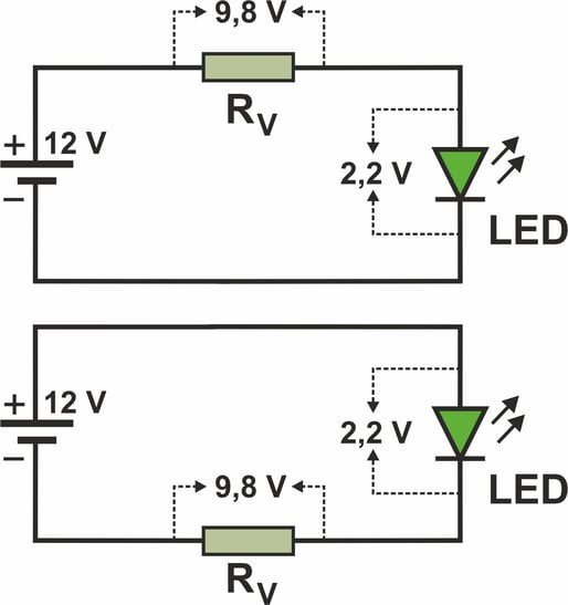
The term LED series resistor indicates that the component must be connected upstream of the LED. Although this is correct, it is not absolutely necessary. In order for the resistor to limit the current through the LED, it only needs to be connected in series with the LED. This is why experts also refer to it as a series resistor. Whether the resistor is inserted into the circuit before the LED or after the LED is technically irrelevant.
Our practical tip: LED connection.
Much more important than the decision as to whether the series resistor is installed before or after the diode is the correct connection of the LED. Especially if the LED is to be operated with DC voltage. This is because the anode of the LED must be connected to the positive terminal. You can find out what the anode is, how to recognize it and other interesting information about LEDs and how to connect them correctly in our LED guide.
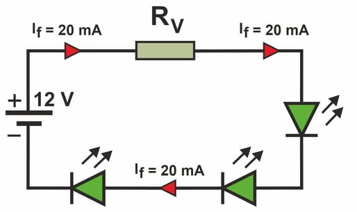
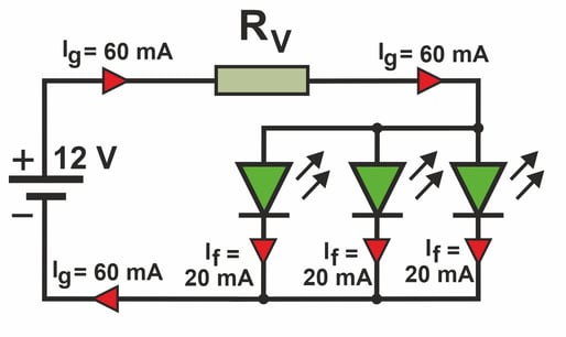
In principle, several LEDs can share a series resistor. This makes sense if, for example, the LEDs are used for lighting purposes on a model railway layout and therefore light up simultaneously and continuously. In this case, the LEDs can be connected in series or in parallel. However, the different arrangements have an effect on the required series resistor. To illustrate the differences, let's look at the green LED mentioned above with 2.2 V and 20 mA in different circuits.
Series connection
When three LEDs are connected in series, the required current of 20 mA flows through all three LEDs and also through the series resistor. However, the voltage drop must not be 9.8 V as mentioned above, but only 5.4 V (12 V - 3 x 2.2 V). As a result, the series resistor must be significantly smaller and, according to Ohm's law, is mathematically only 270 Ω (5.4 V : 0.02 A). The power converted at the resistor is significantly lower than with an LED and is only 0.1 watts.
Disadvantages of the series connection: If one of the three LEDs has an interruption, the entire circuit is interrupted. Current can no longer flow and the two LEDs that are still intact also no longer light up. If an LED has a short circuit, the voltage at the series resistor increases, causing a higher current to flow through the circuit. As a result, there is a risk that the two LEDs that are still intact may also fail.
Parallel connection
If the three LEDs are arranged in parallel, each LED still requires a current of 20 mA. The voltage across all three LEDs is still 2.2 V. As a result, a total current (Ig) of 60 mA (3 x 20 mA) will flow through the series resistor. The size of the resistor must then be selected so that the required 9.8 V drops across the resistor. To ensure this, the series resistor must have a calculated value of 163.33 Ω (9.8 V : 0.06 A). However, the power loss at the resistor is already very considerable at around 0.6 watts.
Disadvantages of the parallel circuit: If one of the three LEDs has an interruption, the remaining LEDs will draw too high a current due to the series resistor being far too small for two LEDs. This can also destroy the LEDs that are still intact. If one LED has a short circuit, all three LEDs are dark and the series resistor has to absorb the full power of around 0.9 W. There is a risk that the resistor will overheat.
Conclusion:
From this point of view, it is definitely an advantageous solution if each LED has its own series resistor that is matched to the respective LED. Especially if the number of LEDs is manageable. This is because if one LED in the system fails, only this one LED no longer emits any light without disrupting or jeopardizing the function of the remaining LEDs. However, this advantage comes at the price of a considerable amount of power loss, which is literally burned up at the series resistors.
If a few LEDs are operated in a circuit, it makes perfect sense to work with series resistors. However, if several hundred or even thousands of LEDs are to be used for lighting purposes, the idea of using series resistors is no longer quite so good.
Many Christmas tree lights are now available with energy-saving LED technology. A single string of lights can also have 100 individual LEDs. If a large tree in the garden is also to be illuminated, ten of these 100 light chains are quickly installed. That's a total of 1000 LEDs, which should provide impressive lighting.
If each LED then had its own series resistor, 1000 resistors would be required in addition to the 1000 LEDs. Even if the resistors are available at low cost, it would be a considerable effort to integrate them into the light chain. If a power of just 0.1 W were to drop across one of these resistors, that would be a whopping 100 W in total, which would be converted into heat with one thousand LEDs.
To avoid this, the manufacturers of fairy lights take a different approach: the power supply is provided by a stabilized power supply unit in which the output voltage is precisely matched to the forward voltage of the LEDs in the fairy lights. The necessary current limitation takes place in the power supply unit, whereby the thin cables of the fairy lights with their relatively high line resistance also contribute to limiting the current.
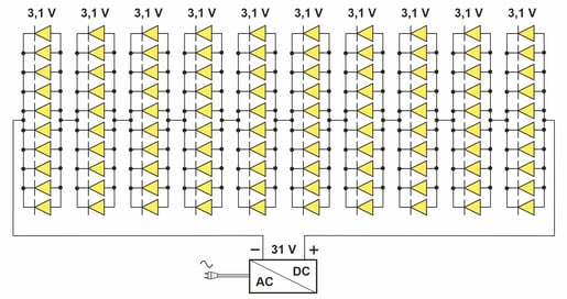
Structure of an LED light chain
The LED light chain itself simply consists of a combination of parallel and series connections. In a string of 100 lights, for example, 10 LEDs are connected in parallel to form an LED group. In the complete light chain, 10 of these groups are then connected in series.
This construction can then be easily operated on a power supply unit with 31 V output voltage. This ensures that the required forward voltage of 3.1 V is available at each individual LED in the light chain. But the best thing is that the high number of LEDs means that the previously mentioned disadvantages of connecting LEDs in series or parallel do not have such a dramatic effect.
Important:
However, the number of defective LEDs must not become too large over time. This is because the more LEDs that fail, the more power the remaining LEDs have to take over. Sooner or later, this can lead to a total failure of the entire light chain.
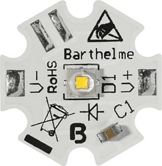
For many powerful high-power LEDs, the technical data often does not specify a forward voltage. This is not necessary, as only the current is the decisive factor for operation.
This is why these LEDs are not connected to a series resistor but, like LED lights, to an LED driver that is matched to the current. As a constant current source, the LED driver automatically adjusts the output voltage until the current required for the LED flows. It does not matter whether one or more LEDs are connected in series at the output. Only the maximum connected load of the LED driver must be observed so that this is not exceeded.

