Multimeter instructions » Correctly measure voltage, current and more
This text is machine translated.
Updated: 15.05.2023 | Reading time: 15 minutes
When an appliance suddenly stops working at home or at work, it is more than annoying. And it is often completely unclear whether the fault lies with the appliance or just the power supply.
How good it is to have a multifunctional measuring device to hand and be able to get to the bottom of the cause of the fault in no time at all.
But how is a multimeter operated correctly? How are the test leads connected correctly? What do I need to pay attention to when measuring? What is the difference between analog and digital? When does a measuring device need to be calibrated?
We answer all these questions and show you what is important when measuring.
The term "meter" is not just a measure of length. A wide variety of measuring devices are often also referred to as "meters".
To differentiate between them, the measured variable is simply stated at the front. For example, terms such as tachometer, thermometer, barometer or hygrometer have become established in our everyday language.
Similarly, in electronics there are voltmeters for measuring voltage, ammeters for measuring current and ohmmeters for measuring resistance. If a measuring device covers several functions at the same time, it is referred to as a multimeter.
Desktop multimeters are available for stationary use in workshops and hand-held multimeters are suitable for mobile use.
An analog multimeter or digital?
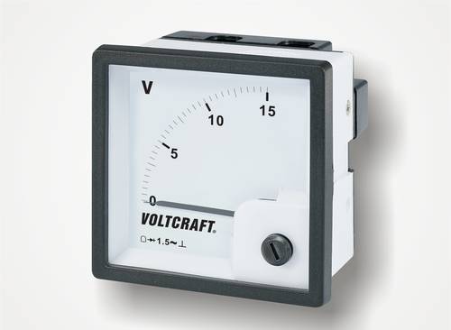
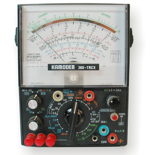
The first multimeters were analog multimeters and had a pointer instrument to display the measured values. However, this often led to reading errors. Either the value was read on the wrong scale or the instrument was viewed from the side.
In order to avoid at least the lateral viewing angle errors (parallax errors), some manufacturers have integrated reflective surfaces into the scales.
If the pointer and the mirror image coincide, you are looking straight at the scale and can read the correct value. With the development of digital technology, multimeters also became digital. Instead of a deflecting pointer, the measured value is now displayed digitally in large digits.
This meant that the mechanically fragile pointer instrument was finally obsolete. The new devices are referred to as digital multimeters or DMMs.
The digital display has proved particularly successful with hand-held multimeters. Because even if large and easy-to-read displays are used, hand-held multimeters are still very compact and extremely handy.
Even an inexpensive digital multimeter can be used to measure a wide range of electrical quantities. But before you start measuring, you need to know which measured value you want to record. As newcomers to measurement technology in particular tend to confuse current and voltage, we explain the most important measured variables in more detail:
Voltage
The electrical voltage is, so to speak, the drive of the electric current. As the electric current is an exchange of charge carriers (electrons), there is a surplus of electrons (-) at one pole of a voltage source and a shortage of electrons (+) at the other pole. The greater the difference between excess and deficiency, the higher the voltage. In simple terms, you can say that the voltage describes the force or strength of a voltage source.
The formula symbol for the voltage is U and the unit is 1 volt (V).
Alternating voltage
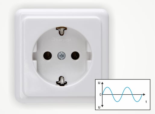
Sockets emit an alternating voltage.
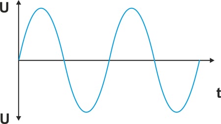
If the voltage level changes periodically and the mean values of the positive and negative components are equal, this is referred to as alternating voltage V/AC (AC = alternating current). Typical voltage sources for alternating voltage are mains sockets or mains transformers.
Electricity
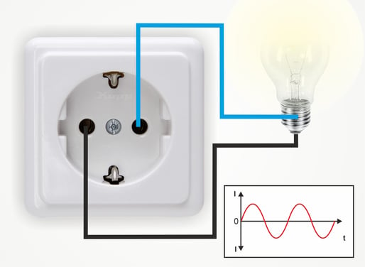
If the two poles of a voltage source are conductively connected to each other via a load, an electric current flows. This means that electrons are fed into the circuit on the side of the voltage source with the excess electrons. On the side of the voltage source with a shortage of electrons, electrons are withdrawn from the circuit.
In principle, the voltage source attempts to balance out the excess/shortage situation via the circuit. The level of the current depends on the level of the voltage at the voltage source and the resistance of the load.
The formula symbol for the current is I and the unit is 1 ampere (A).
Depending on the equipment, digital multimeters offer even more measurement options.
Resistance
Even in the lowest price category, many digital multimeters offer the option of measuring continuity and resistance.
This makes it easy to test cables, switches or even fuses.
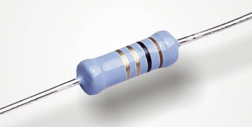
On the other hand, the exact values of resistances can also be measured.
The formula symbol for resistance is R and the unit is 1 Ohm (Ω).
Capacity
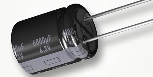
Capacitance measurement for capacitors works in a similar way to resistors. However, instead of the direct voltage (DC) for resistance measurement, the digital multimeter now generates an alternating voltage.
As a result, the capacitor to be tested is constantly charged and discharged with alternating polarity. The measuring device can determine and display the capacitance of the capacitor based on the charging current flowing during this process. The formula symbol for the electrical capacitance is C and the unit is 1 farad (F).
Diodes
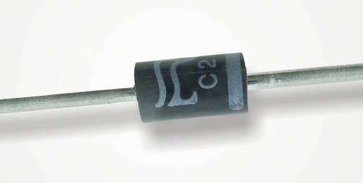
The PN junctions of diodes can be tested using the diode test function. This means that the digital multimeter is used to check whether the respective semiconductor allows the current to pass in one direction and reliably blocks it in the other direction.
However, the diode test function can also be used to test transistors in the same way. This is because transistors have a diode path between the base (B) and emitter (E) as well as between the base (B) and collector (C).
Temperature
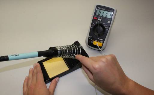
Temperature measurement with a digital multimeter is usually possible with a sensor specially adapted to the measuring device.
These sensors are mostly nickel-chromium-nickel sensors (NiCrNi sensors) type K, which emit a voltage depending on the temperature.
This temperature sensor voltage is recorded by the measuring device and the voltage value is assigned to a temperature.
Frequency
When measuring frequency, the measuring device determines how often a signal oscillates around an average value per second.
It is important to note that a positive and a negative value always result in an oscillation. In the case of the mains frequency of 50 Hz, this results in 50 positive half-waves and 50 negative half-waves. The voltage therefore changes polarity 100 times per second.
The formula symbol for the frequency is f and the unit is 1 Hertz (Hz).
Popular digital multimeters (DMM)
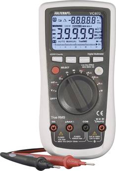
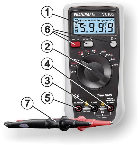
To ensure that voltage, current or other electrical values are measured accurately, the digital measuring device must be set up and connected correctly. Various operating elements and connections are available for this purpose, which we will demonstrate using a VOLTCRAFT multimeter from the VC 100 series as an example:
Operating elements of a multimeter
1. Display
The display not only shows the measurement result. Often, other information such as the measuring range, auto ranging and the voltage level of the internal battery are also displayed.
2. Rotary switch for manual measuring range selection
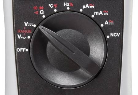
The measuring range is set manually using the rotary switch. As the multimeter has an auto range function, there is only one switch position each for DC and AC voltage. The measuring device determines the voltage measuring range or the decimal point in the display itself based on the measured values.
In contrast, when measuring current, the user must select whether the measured current is in the µA range, the mA range or the ampere range by setting the switch.
3. Measuring socket (-)
The black measuring cable is connected to this socket. It serves as a common earth potential (COM) for voltage and current measurements.
4. Measuring socket (+)
The red test lead is connected to this socket. With the exception of current measurements from 0.2 to 10 A, this socket serves as a common positive potential for voltage and current measurements.
5. Measuring socket 10 A
For current measurements from 0.2 to 10 amperes, this socket must be used as a positive connection for the test leads.
6. Function switch
These switches can be used to activate various measuring and special functions.
7. Test leads
The measuring cables are used to connect the measuring device to the object to be measured.
Connecting the test leads to the multimeter
If voltages and low currents are to be measured or components tested, the red test lead must be plugged into the test socket (4). The black test lead must be connected to the middle test socket (3).
As a rule, the measuring device sockets are clearly labeled to prevent incorrect connection of the test leads. If in doubt, please refer to the enclosed operating instructions.
Select the correct measuring range
Before the measurement can begin, the required measuring range (e.g. voltage, current or resistance) must be selected using the rotary switch. This is very important and must be done carefully.
This is because the measuring device behaves differently depending on which measuring range has been set.
If the digital multimeter has been set to measure voltage, the measuring device has a high resistance. This means that the internal resistance of the measuring device is very high.
If the digital multimeter has been set to measure current, the measuring device has a low resistance. This means that the internal resistance of the measuring device is very low.
Important:
If, for example, a voltage measurement is planned and the measuring device has been set to a current measuring range by mistake, the measuring device behaves like a wire bridge and thus represents a short circuit! The measuring circuit and the measuring device can be destroyed!
Our practical tip:
Many multimeters are equipped with fuses that trigger if the current is too high due to incorrect operation. If a fault occurs, it may not be necessary to dispose of the entire measuring device, but only to replace the fuse. Some manufacturers even include replacement fuses with their devices.
Switch on the multimeter
Many multimeters switch on automatically when the rotary switch is moved from the "OFF" position to the required measuring range. After the measurement, the rotary switch must be returned to the "OFF" position. Other multimeters have an additional on/off switch with which the device is switched on.
To conserve the internal battery, most multimeters switch off automatically after a period of inactivity.
If the test leads have been connected correctly and the correct measuring range has been set, the multimeter is ready for the measurement.
Voltage measurement is one of the simplest measurements in electronics or electrical engineering. This is because the multimeter is simply connected in parallel to the voltage source or the object to be measured.
To prevent excessive current flowing through the measuring device, which could falsify the measurement result, it has a very high internal resistance when measuring voltage.
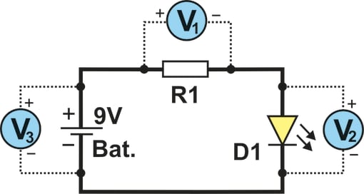
The illustration opposite shows a simple circuit with a 9 V battery, a series resistor for voltage reduction (R1) and an LED (D1).
If the voltage is to be measured via the resistor, the digital multimeter must operate as a voltmeter (V) and be connected according to V1. If the voltage is to be measured via the LED, the digital multimeter must be connected to V2.
Both voltages together must result in the battery voltage. To measure this, the multimeter must be connected to V3.
Measure correctly!
The polarity of the measuring leads is important when measuring voltage. If the measuring tips are placed on the measuring points the wrong way round, the pointer of an analog measuring device would swing to the left. With a digital multimeter, a negative measured value (e.g. -5.62 V) would be displayed.
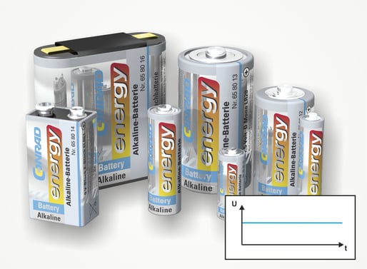
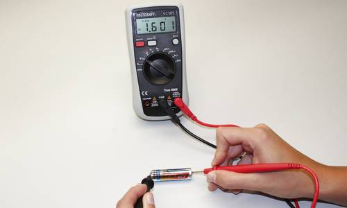
Test the battery with a multimeter
Although voltage measurement on a battery is often practiced, it is not necessarily very meaningful. This is because the battery is not sufficiently loaded by the high-impedance measuring device.
It is therefore quite possible that the full voltage is displayed during the measurement, but the battery collapses after just a short period of use.
If the multimeter displays a voltage value that is far too low even when measuring without a load, the battery can be disposed of immediately
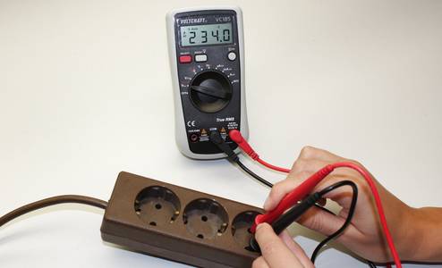
Check the mains voltage with the multimeter
When renovating, it is often unavoidable that lamps or sockets have to be dismantled or relocated. It is therefore vital to check whether voltage is present on the cables and connections before loosening the terminal connections. Suitable multimeters are very useful here. However, the user must know exactly what to do.
Measurements in circuits >33 V/AC and >70 V/DC may only be carried out by specialists and trained persons who are familiar with the relevant regulations and the resulting dangers.
Important: The correct measuring range is crucial
The 230 V mains voltage is an alternating voltage. It is therefore essential that the multimeter is set to AC voltage. If it is set to DC voltage, it will display 0 V or only a low value of a few volts, even if the full mains voltage is present. This is a measurement error that can have fatal consequences.
Voltage measurements in electronics
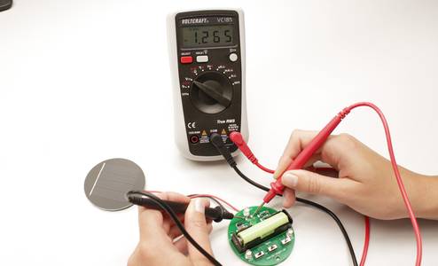
Voltage measurements in electronics are also easy to carry out. This is because the measuring tips only need to be placed on the soldering pads or on the connecting legs of the components.
However, some electronic know-how is required to assess the measurement results and find the fault in the circuit.
LED solar lights are ideal for getting started with measurement technology. This is because the circuit structure is straightforward and, with a little practice, it soon becomes clear why the expensive stainless steel light is no longer working.
Check the lambda sensor with the multimeter
Experienced car mechanics also like to use a digital multimeter for electronics problems. Specialists can even use it to test the functionality of the lambda sensor. Especially if no OBD diagnostic device is available for reading fault codes.
However, you need to know exactly which cables are used to output the sensor voltage and which connections of the sensor are used for heating.
Even if a digital multimeter is basically far too slow to accurately display the rapid voltage jumps of the probe, you can at least see in the range of 0.2 to 0.8 V whether the probe is exhibiting control behavior.
Measuring the current with a multimeter is somewhat more complex. This is because the circuit must be disconnected at any point and the measuring device connected to the circuit. This is the only way to measure the actual current flowing.
The measuring device has a very low internal resistance so that it does not represent an additional resistance in the circuit. It can be regarded as a "wire bridge".
As with voltage measurement, the correct polarity of the test leads must also be ensured when measuring current. If the polarity is incorrect, the display will show a negative measured value.
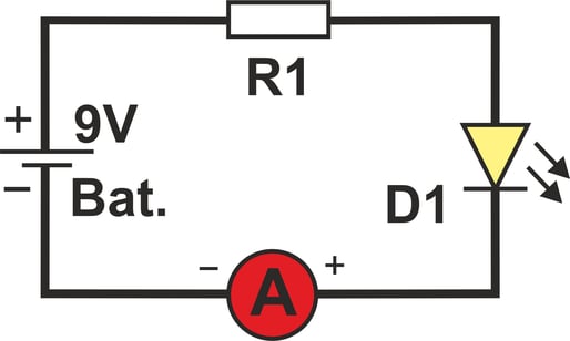
The illustration opposite shows a simple circuit with a 9 V battery, a series resistor (R1) and an LED (D1).
If the current is to be measured within this circuit, the digital multimeter must act as an ammeter (A). It is absolutely irrelevant where the circuit is disconnected and the ammeter is connected in between. This is because the current is the same at every point in a circuit.
Our practical tip:
If it is not clear how high the current to be measured will be (within the permissible limits of the measuring device), always start in the largest measuring range. If necessary, you can switch to a smaller measuring range in order to carry out more precise measurements.
Note:
Current measurement is rarely carried out during servicing and repairs, as it is not as helpful for troubleshooting as voltage measurement. After all, a voltage must first be present for a current to flow. However, there are some areas where current measurement is still important.
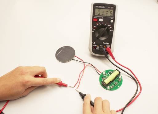
There are two important parameters for solar modules that can be checked with a multimeter. The first value is the open-circuit voltage that the solar module generates when the sun shines on the module at a 90° angle at full power. For correct measurement, only the high-impedance voltmeter may be connected to the solar module.
The second important value is the short-circuit current. In contrast to rechargeable batteries or batteries, a solar module can be short-circuited without hesitation. The current flowing in this case is specified in the technical data, as is the open-circuit voltage. As both values can be easily measured with a multimeter, the performance of a solar module can be tested quickly and easily.
The charging current can also be measured during operation.
Current clamp for multimeter
When particularly high currents flow in the automotive sector or in electric model airplanes, it is difficult to measure the current.
This is because it is not so easy to disconnect the circuit and connect the measuring device in between. For this reason, current clamps were developed years ago.
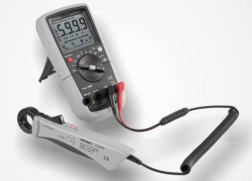
Every current-carrying conductor generates a magnetic field. The strength of the magnetic field depends on the level of the current.
A current clamp grips the conductor and can generate a voltage based on the magnetic field. This voltage is measured by the multimeter and assigned to a current value, which is then shown on the display.
As ingeniously simple as this method is, it unfortunately only works with individual conductors.
Unfortunately, a current clamp does not work on a power extension cable with several conductors carrying current within a sheath.
Due to the different current directions within the cable, the magnetic fields cancel each other out.
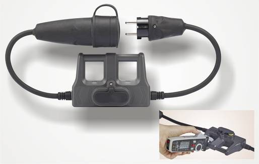
For this case, however, there are special measuring adapters that allow each current-carrying conductor to be individually covered by the clamp ammeter.
As already mentioned, a sensor suitable for the measuring device is required for temperature measurement.
These probes are either supplied with the multimeter or offered as an option.
Depending on the version of the multimeter, the temperature sensor is connected instead of the measuring leads or, in the case of older devices, to separately designated flat plug sockets.
The multimeter assigns the determined sensor values to a temperature and shows them on the display.
In addition to voltage and current measurement, many multimeters also offer the option of testing components. It is important to note that the components must be tested when they are removed and de-energized. Capacitors may have a residual charge that must be discharged before the measurement.
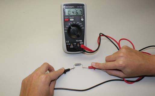
Measuring resistance with a multimeter
When measuring resistance, the multimeter's battery serves as a voltage source.
This means that when measuring resistance, a low DC voltage is present at the measuring tips of the multimeter when the rotary switch is set to the "Ohm" measuring range.
When the two measuring tips are connected to the two terminals of the resistor, a low measuring current flows.
Depending on how high the current is, the multimeter determines a resistance value and displays it together with the measuring range (Ω, kΩ or MΩ).
Multimeter as continuity tester
In addition to measuring resistance, some multimeters also offer a continuity function. With this function, low-resistance components such as fuses, switches or conductor tracks can be tested quickly and easily. The electrically conductive continuity is also displayed acoustically so that you can concentrate on the test object. It is therefore not necessary to read the resistance value on the display.
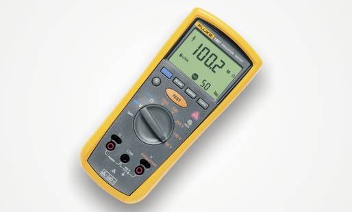
Measure insulation resistance with a multimeter
The measurement of insulation resistance is required by law for electrical systems and equipment as well as for electric vehicles.
This allows defects that affect functionality and safety to be detected and rectified at an early stage.
As a standard multimeter cannot generate the required measuring voltage of up to 1000 V/DC, special insulation measuring devices are required for insulation measurement.
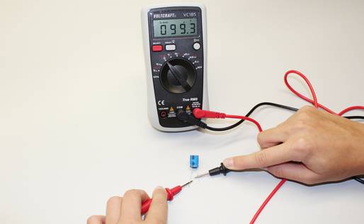
Check capacitor with a multimeter
The capacitance measurement is carried out in the same way as the resistance measurement. This means that the capacitor to be measured is connected to the two measuring leads.
When measuring capacitance, the multimeter must output an AC voltage instead of the DC voltage for the resistance measurement. Only in this way can the capacitor be continuously charged alternately.
The current that flows when the polarity of the capacitor is constantly reversed depends on the capacitance of the capacitor. This charging current is measured by the multimeter and assigned to a capacitance value, which is then displayed.
Check diodes with a multimeter
As with the resistance measurement, the multimeter outputs a voltage on the test leads during the diode test. If the polarity of the voltage at the test probes is such that the diode blocks and does not allow current to flow, no voltage is shown on the display.
If the polarity of the voltage at the measuring tips is such that the diode allows current to flow, the forward voltage of the diode is shown on the display.
For intact standard diodes, the forward voltage is approx. 0.6 - 0.7 V and for Schottky diodes approx. 0.4 V. For LEDs, the forward voltage depends on the type and color and can range from 1.6 - 3.7 V on average.
Note:
With some digital multimeters, the resistance value is displayed instead of the forward voltage. In the reverse direction, the resistance is infinite and in the forward direction, the resistance is between 400 and 800 ohms, depending on the type of diode.
You can often find terms in the descriptions of digital multimeters that are not clearly explained. We therefore want to explain the most important technical terms in more detail.
Auto Range
Multimeters with Auto Range function recognize the range that needs to be displayed based on the measured value. For example, when measuring resistance, not only the measured value of e.g. 10.8 is displayed, but also the measuring range Ω, kΩ or MΩ. Digital multimeters without Auto Ranging have separate switch positions for the different measuring ranges.
True RMS
The term True RMS or the abbreviation RMS stands for Root Mean Square and means root mean square or effective value. A TRMS multimeter is therefore able to display the true RMS value.
This is important for asymmetrical alternating voltages or alternating currents that do not correspond to the basic form of a sine wave. Such voltages are generated, for example, by dimmers, pulsed switching regulators or pulsed chargers. Conventional average value measuring devices can sometimes show large deviations in the measurement results for these special measurement tasks.
Counts
The resolution of the display is defined with the Counts specification. A multimeter with 2000 counts can display a range of 0 - 1999. With 4000 counts, the display range is 0 - 3999. The position of the decimal point is determined automatically by the measuring device. A meter with 2000 counts can therefore display voltages up to 199.9 V with one decimal place. If a higher voltage (e.g. 230.6 V) is measured, the decimal place is omitted and 230 V is displayed. A meter with 4000 counts (0 - 3999) can display the measured value of 230.6 V correctly. The resolution of the measured value also depends on the number of counts. In the measuring range of 20 V, 2000 counts result in a resolution of 10 mV (20 V : 2000 = 0.01 V). At 4000 counts, the resolution would be 0.005 V or 5 mV.
CAT
The abbreviation CAT describes the measurement category for which the measuring device is designed. The following categories are defined according to EN 61010-1:
CAT I: For measuring battery-operated circuits that have no direct connection to the mains. Examples: Flashlights, remote controls or vehicle electrics.
CAT II: For measurements on circuits that have a direct connection to the mains via a mains plug. Examples: Household appliances or power tools.
CAT III: For measurement within the building installation where the loads are permanently wired to the power grid. Examples: Sub-distribution boards, sockets or lamps
CAT IV: For measurements at the source of the low-voltage installation. Examples: Electricity meter, main connection, main fuses, photovoltaic systems or electrically powered vehicles.
Calibration
Users who have to document their measurement results in a traceable manner due to applicable regulations use digital multimeters calibrated in accordance with DIN or ISO. With a calibrated measuring device, it is verifiably documented that it works within the permissible tolerances. The calibrated measuring device has not been tampered with or modified. If necessary, measuring devices can be calibrated before purchase. Calibration must be repeated at regular intervals.
Duty Cycle
The utilization factor or duty cycle indicates the ratio of the positive pulse (switch-on pulse) to the period duration for a square-wave signal. At a frequency of 50 Hz, the period duration is 20 ms. If the positive pulse has a width of 1 ms, the duty cycle is 5%.
A small digital handheld multimeter belongs in every household. After all, these multifunctional measuring aids are perfect for finding electrical faults in systems, vehicles or appliances. But that's not all: even in the lowest price range, you can now get high-quality measuring technology with many ingenious additional functions. And once the first voltage measurements have been successfully completed, you will very quickly discover other possible uses for your measuring device.
