Alternating current, three-phase current & direct current » Differences simply explained
Updated: 05.04.2022 Reading time: 13 minutes
This text is machine translated.
Anyone who studies electrical engineering and electronics in depth will come across the terms “current” and “voltage” again and again. Beginners in particular quickly lose track of what is meant by direct voltage, alternating voltage, three-phase current or AC and DC.
When the formula symbols also come into play, the confusion is complete. For this reason, we have explained some of the terms relating to current and voltage in an easy-to-understand way.
In order to understand the subject of electricity, you need to know exactly what electric current is. All further information and explanations can then be easily based on this.
In electricity theory, current is defined as the transport of electrical charge carriers. Charge carriers can be electrons, for example, which flow in an electrical conductor.
To do this, the atoms of the electrical conductor must be designed in such a way that they can easily release electrons and also easily absorb them again. Many metals, such as aluminum or copper, have this advantageous property. In contrast, there are materials that do not release their electrons. These materials are then used as insulators.
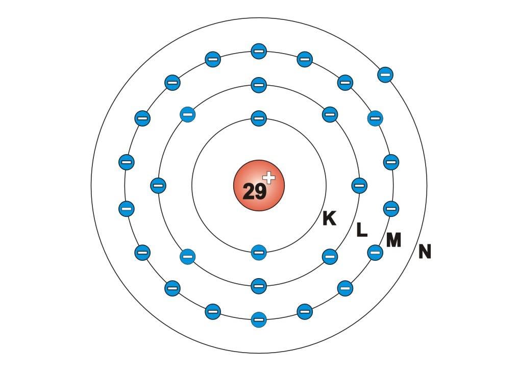
If you take a closer look at Bohr's atomic model, you can see that electrons orbit the atomic nucleus in different orbits. In the case of copper with atomic number 29, there are 29 electrons, whereby there is only one electron (valence electron) in the outermost shell, the valence shell.
However, the relationship between the atomic nucleus and the electron orbit is not correct in the attached drawing. In the case of an atomic nucleus with a diameter of 5 - 6 cm, an electron would be the size of a pinhead and would orbit the nucleus at a distance of approx. 100 meters.
As the atoms in metals have a lattice structure, it can happen that the valence electron comes very close to the nucleus of a “neighboring atom”. As a result, it loses the bond to its “own” atomic nucleus and can move freely in the conductor.
In order for these free electrons to move through the conductor and for an electric current to flow, an external driving force must act on the conductor or the electrons in the conductor. This force is generated by the electrical voltage.
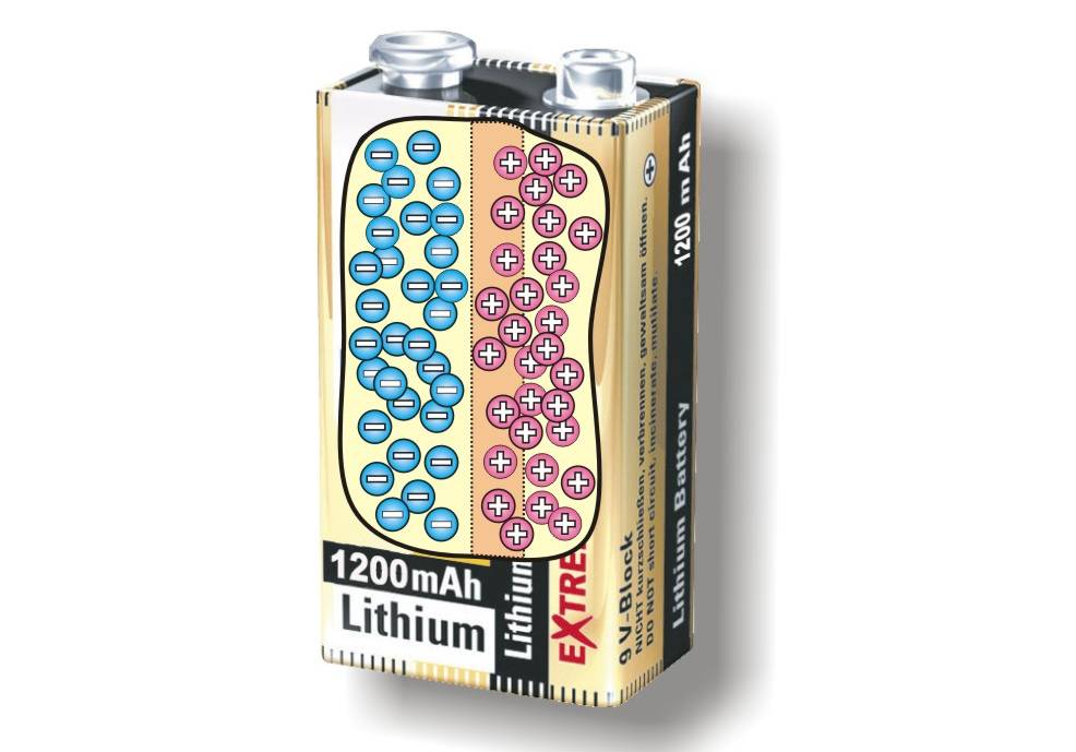
The electrical voltage is explained as the driving force for the flow of electrical current. A voltage source therefore requires two connections. One connection must have a surplus of electrons (negative pole) and the other connection must have a shortage of electrons (positive pole). The way in which the potential difference between the two connections is generated in a voltage source is quite different.
Essentially, electromagnetic induction is used for this purpose. This starts with a bicycle dynamo with low energy and extends to gigantic power station generators. In batteries or accumulators, electrochemical processes are used to generate voltage.
Another way of generating voltage is, for example, static charging by convection, which can be found in thunderclouds or induction machines.
The formula symbol for the voltage is U and the unit is 1 volt.
Regardless of the type of voltage generation, the effect of the electrical voltage is always the same:
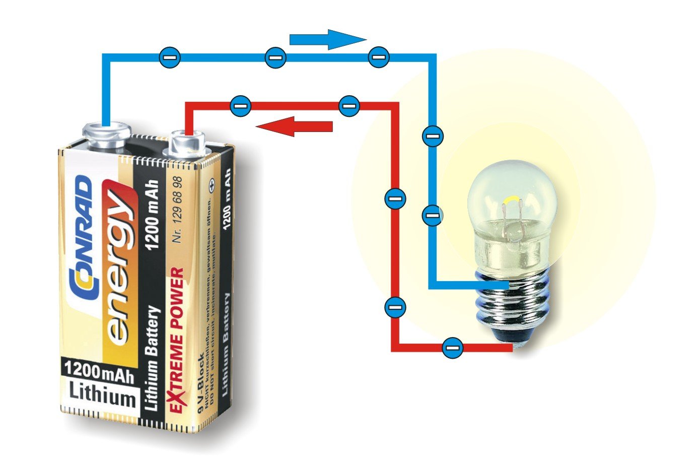
As soon as the two poles of a voltage source are connected to an electrical conductor, current flows. This means that free electrons are withdrawn from the conductor on the side with a shortage of electrons. At the same time, electrons are released into the conductor on the side with an excess of electrons.
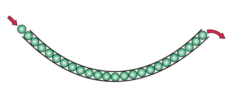
This works in a similar way to a tube (conductor) filled with balls (electrons). If you insert another ball into the tube on one side, a ball falls out on the other side at the same time.
It is the same with an electric circuit. The effect of the voltage, i.e. the pressure on the balls in the tube, is transmitted at almost the speed of light. The actual movement of the individual electrons, however, is approx. 1 mm/s.
The formula symbol for the current is I and the unit is 1 ampere.
Certain conditions must be met for electricity to flow:
1. an electrical voltage must be present
As the electrical voltage is the driving force for the current, no current can flow without voltage. At the latest when you are sitting in a cold and dark apartment during a power failure, this connection becomes clearly noticeable.
2. the circuit must be closed
The circuit must be closed so that the voltage source can feed electrons into the circuit on the one hand and withdraw them on the other.
If the circuit is interrupted by a switch, no more current can flow. Even if the voltage is still present.
The amount of current flowing through a circuit initially depends on the voltage level of the power source. If, for example, the voltage of a flashlight drops because the batteries run out, the current also decreases. The light becomes dimmer and dimmer until it finally goes out completely.
However, the resistance of the circuit or consumer also plays a decisive role.
In a car, several hundred amperes flow through the starter motor during the starting process. The parking light bulb, on the other hand, only requires a few milliamperes. This is despite the fact that both consumers are connected to the same car battery and have the same operating voltage of 12 V. The reason for this lies in the electrical resistance of the consumers. This is extremely low for an electric starter and very high for a parking light bulb.
The formula symbol for the resistance is R and the unit is 1 Ohm (Ω).
Ohm's law
Ohm's law defines the relationship between voltage, current and resistance:
Resistance = voltage : current (R = U : I)
According to this formula, one value can always be calculated if the other two are known. The converted formulas are then
U = R x I or I = U : R
Even before the existence of atoms and electrons was known, the movement of positively charged charge carriers (ions) in electrolytes could be detected.
As the charge carriers moved from the positive pole to the negative pole, it was assumed that the technical direction of the current was from positive to negative.
This approach has been retained to this day. In the circuit diagrams of a wide variety of devices, the components drawn, such as diodes or transistors, are designed according to this direction of current flow.
The physical current direction, on the other hand, describes the actual electron movement, which runs from minus to plus.
A DC voltage is a voltage at which the electrons always move in one direction. The polarity of the voltage source is therefore always the same. The voltage level, on the other hand, does not necessarily always have to be the same.
Classic energy sources for generating DC voltage are batteries and rechargeable batteries, where the voltage level decreases to a greater or lesser extent during discharge.
In addition, most power supply units also generate a DC voltage, although they are supplied with AC voltage. With stabilized power supply units, in addition to the constant current direction, great importance is also attached to an absolutely constant voltage level.
As the voltage has the same polarity continuously, the current also flows continuously in the same direction. However, the direct current can vary in magnitude depending on the voltage. The initial letters of the English term Direct Current (DC) are also used in German for direct current.
Note:
The great advantage of direct voltage or direct current is the possibility of storage. With the help of batteries or rechargeable batteries, electrical energy can be stored in an ideal way for mobile use.
An alternating voltage is a voltage in which the polarity changes periodically and the voltage value therefore changes continuously. The most common AC voltage is the sinusoidal AC voltage of the public power grid. It is very easy to see how a sinusoidal alternating voltage is generated if you take a closer look at an electricity generator.
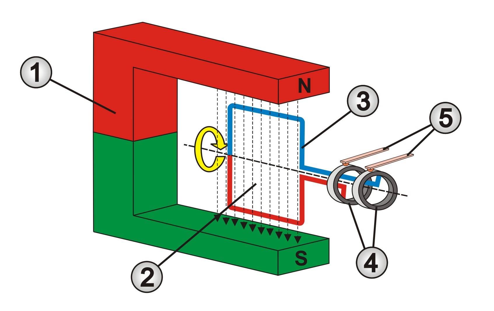
As with a DC electric motor, the generator consists of a permanent magnet (1) with a north pole (red) and south pole (green), which serves as the stator. A few arrows (2) can be seen between the two poles to visually represent the invisible magnetic field.
A rotatable coil (3) is arranged in this magnetic field. To simplify the illustration, the rotor coil in the picture only has one winding. The two ends of the coil are connected with slip rings (4) so that the voltage of the coil can be dissipated to the outside via sliding contacts (5).
If the coil is aligned vertically as shown in the picture, the horizontally arranged parts of the coil cross a large number of magnetic field lines during movement. As a result, the voltage induced in the coil is very high at this moment.
If the coil is aligned horizontally, the horizontal coil wires move parallel to the magnetic field lines. As no magnetic field lines are crossed in this case, the voltage induced in the coil is zero.
As the coil rotates at a constant speed, this results in a sinusoidal alternating voltage. In the following video, the coil can be seen directly from the front.
With an ohmic load, such as an incandescent lamp, the current behaves in the same way as the voltage. This means that the current rises at the same time as the voltage, falls again after the peak value and changes direction at the negative half-wave. This is why it is also referred to as alternating current. The initial letters of the English term Alternated Current (AC) are also used in German for alternating current.
Note:
The great advantage of alternating voltage or alternating current is the possibility of transformation. With two coils on an iron core (transformer), an alternating voltage of e.g. 230 V can easily be converted into 12 V alternating voltage.
As part of the harmonization process, the mains voltage was set at a uniform 230 V throughout Europe in 1987. Since 2009, the maximum permissible voltage fluctuation has been ± 23 V.
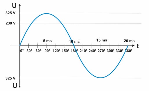
This means that the mains voltage can range from 207 V to 253 V. The specified voltage values describe the effective voltage. This means that if a heating resistor is connected to the 230 V mains voltage of the socket, it achieves the same heating output as if it were operated at a DC voltage of 230 V.
However, as the voltage always returns to 0 volts between the half-waves with a sinusoidal alternating voltage, the voltage peaks (Us) must therefore be significantly higher than 230 V. In practice, the value is approx. 325 V. The attached diagram illustrates these relationships.
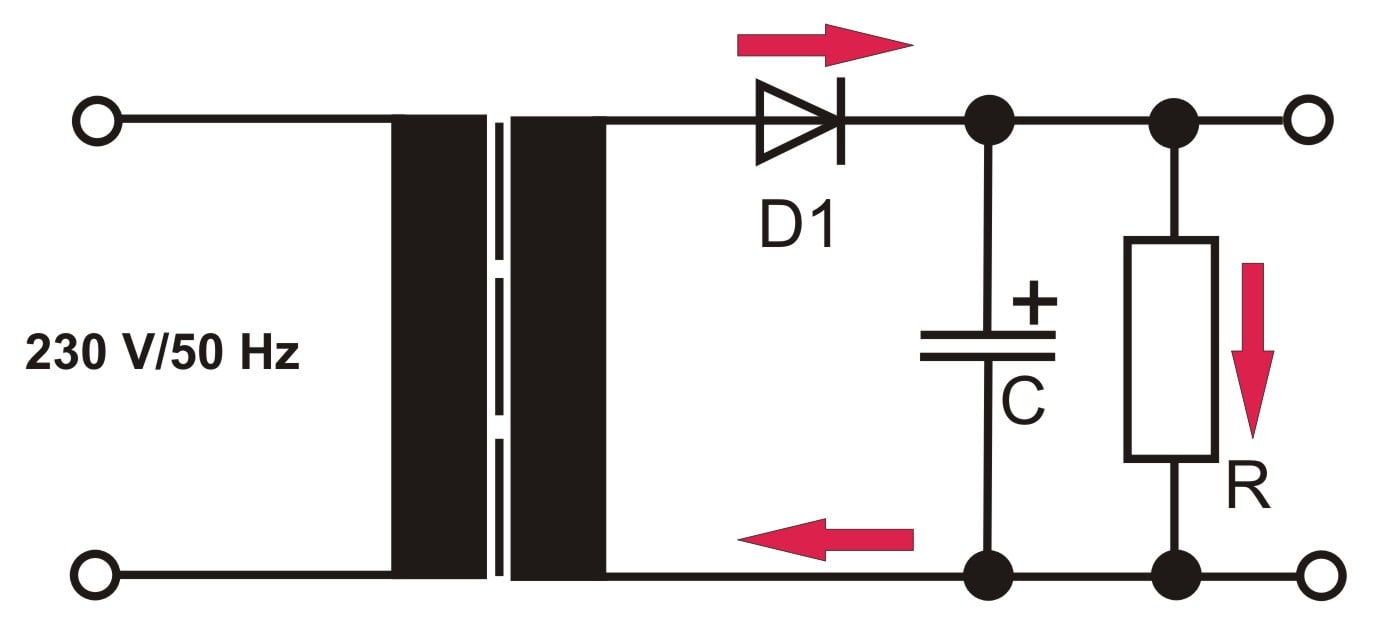
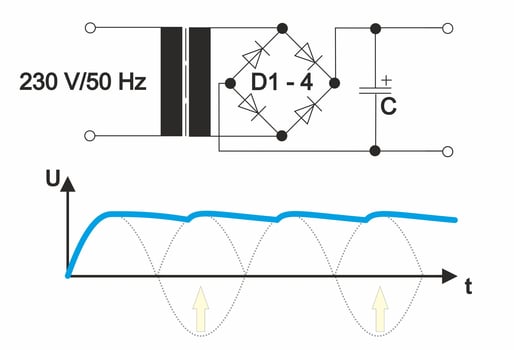
Mixed voltages are when a DC voltage is superimposed on an AC voltage. In practice, mixed voltages are often found in unstabilized plug-in power supply units. These power supply units usually contain a bridge rectifier (diode D1 - 4), which folds the negative half-wave upwards into the positive voltage range. Without a filter capacitor (C), which keeps the output voltage at approximately the same level (see blue line), the voltage between the half-waves would always drop to zero.
However, as the filter capacitor always discharges slightly between the individual voltage peaks of the sine half-waves, the DC voltage constantly fluctuates in level. Experts refer to this as voltage ripple. A constantly changing mixed current then flows in accordance with the voltage changes in the mixed voltage. This means that the direct current fluctuates to the rhythm of the superimposed alternating voltage.
The residual ripple of a rectified power supply voltage smoothed with a capacitor (see also section Mixed voltages) should be as low as possible. This is particularly important for power supply units in audio amplifiers.
This is why amplifier power supplies are also fitted with large capacitors with a high capacity to smooth the operating voltage. This is because these capacitors must serve as a voltage source for the amplifier between the half-waves. If the capacitors are too small or have aged over time and thus dried out, they generate too much ripple, which is then noticeable as a humming sound in the loudspeakers. This effect can often be observed in old radios. For this reason, the residual ripple of the power supply unit is also referred to as hum voltage.
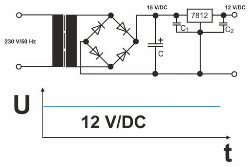
In order to obtain an absolutely clean DC voltage, voltage stabilization stages or fixed voltage regulators are often used. However, for this stabilization to work reliably, the input voltage must be at a slightly higher level than is required at the output for the loads.
A mains voltage of 230 V is perfectly adequate for many household and office applications and consumers. However, this is often not the case in trade or industry.
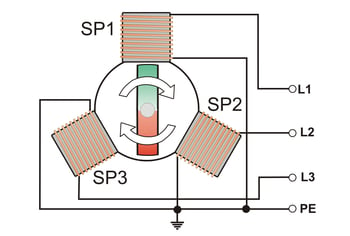
Motors, large machines and systems require more power for the electrical energy supply. For this reason, not just one, but three coils are used in the power generators to generate electricity. The middle connection of the three coils is combined in a common point and connected to earth. The other three coil ends are routed to the outside as individual phases L1, L2 and L3.
Note:
Whether a coil rotates in a magnetic field of a stationary magnet or vice versa is irrelevant to the functional principle.
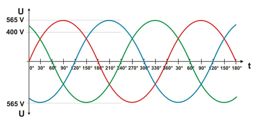
The three coils are mechanically offset from each other by 120°. Consequently, the three sine waves are also offset by 120° in time.
If the alternating voltage is measured at one coil, this results in an effective value of 230 V. This voltage is used in building installations for sockets and lighting.
However, if the voltage is measured between two phases, the voltage values of both coils are added together. As a result, the effective value here is 400 V and the peak value is 565 V.
As three-phase alternating current is primarily used to supply large electric motors, this type of energy supply has also become known colloquially as heavy current, three-phase current or power current. Accordingly, the electric motors are also referred to as three-phase electric motors or three-phase motors.
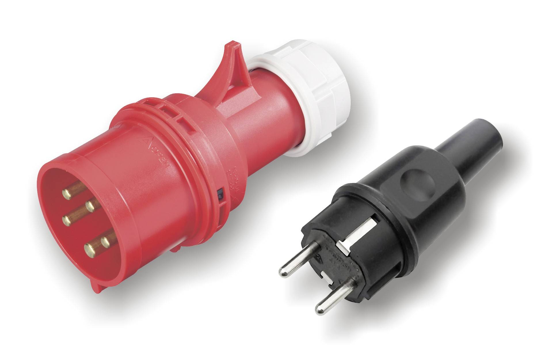
In contrast to the three-pin safety sockets that can be found in every office and workshop, the sockets or plugs for three-phase alternating current or three-phase current have five plug contacts and are known as CEE plugs. The plug size varies depending on the amperage (e.g. 16, 32 or 63 A).
Energy suppliers are interested in loading all three outer conductors or phases of the power grid equally. This is why all three phases are made available to the end consumer for the building installation. Even if the end consumer does not require a three-phase connection.
It is then the task of the electrical installation to distribute the existing loads evenly across the three phases by means of appropriate distribution.
Why is dangerous 230 V used for the power supply of buildings?
The high voltage means that the current can be kept low despite the high power. This makes it possible to use cables with 1.5 mm² or 2.5 mm² for the electrical installation and thus keep costs manageable.
Why is high voltage used for overhead lines?
Power lines have an ohmic resistance that cannot be avoided. The extent of the voltage loss due to the line resistance depends on how much current flows through the line. In order to keep the current flow as low as possible, the voltage is transformed to several 100,000 V for long distances. This ensures that as little power as possible is lost during energy transmission. At the destination, the high voltage is transformed down in stages via substations and finally fed into the 230 V low-voltage grid.
Why can birds sit on power lines without being harmed?
The birds only sit on one conductor, whereby the distance between the legs is so small that it is virtually the same voltage potential. It becomes dangerous when birds with a large wingspan come close to two lines or a line and the earthed pylon with the tips of their wings. This can easily lead to dangerous voltage flashovers.
When do voltages become dangerous?
According to the German Association for Electrical, Electronic & Information Technologies (VDE), the maximum contact voltage is 50 V/AC and 120 V/DC. The current flowing depends on the body resistance. With an alternating current of 50 Hz, even 45 mA can cause serious health problems. This is why residual current circuit breakers trip at 30 mA.
Are electric pasture fences dangerous for people?
Basically not! Although the electric fence generators generate very high voltages of several thousand volts, the voltage collapses immediately as soon as even a small current flows. However, people with a heart condition should not deliberately touch a live electric fence wire.
Why do you sometimes get an electric shock when you touch doors?
This happens when you walk over a carpet with well-insulated shoes. The friction causes an electrostatic charge to build up. The material with the weaker electron bond releases electrons to the material with the stronger electron bond. This creates a potential difference. When a door or metal shelf is touched, the electrical energy of the potential difference is discharged, which is felt as a brief but unpleasant “electric shock”. However, due to the low electrical power, this effect is not dangerous.
