Electric motors » Structure, function, and types explained simply
Updated: May 17, 2023 | Reading time: 17 minutes
This text is machine translated.
Whenever something in our modern world turns or moves at the touch of a button, electric motors are usually at work. However, very few people are aware of this when using them. Even though they bring toothbrushes, mixers, washing machines, roller blinds, garage doors, and countless other devices and machines to life every day at the touch of a button.
This apparent disregard is, in a sense, quite understandable, as electric motors often perform their duties hidden away, quietly and inconspicuously, for years on end.
However, electric motors are now once again attracting increased public interest. This is because these powerful electric devices do not just generate mechanical energy. They are well on their way to replacing combustion engines in our motor vehicles. This is yet another reason to take a closer look at electric motors.
Simply put, an electric motor, or e-motor, is an electromechanical converter that generates mechanical power from electrical power.
Electric motors therefore have a power connection to which electrical energy is supplied.
The mechanical output, which in the simplest case is designed as a shaft, rotates and serves as a drive for machines and devices.
The operating principle of an electric motor is based on the magnetic effect of electric current.
The electric motor was not invented by a single person. Rather, the discoveries and inventions of many different people contributed to the development of the electric motor:
In 1820, Hans Christian Ørsted discovered that conductors carrying electric current generate a magnetic field. He was the first to use electric current to generate a magnetic field and set a compass needle in motion. In the same year, Frenchman André-Marie Ampére invented the cylinder coil.
In 1821, Michael Faraday presented his findings on “electromagnetic rotation.” In his designs, a movable conductor rotated around a fixed magnet or a movable magnet rotated around a fixed conductor.
In 1822, mathematician and physicist Peter Barlow built the Barlow wheel, named after him. The wheel with metal spokes rotated between the pole pieces of a U-shaped magnet.
In 1825, William Sturgeon invented the first functional electromagnet with an iron core to amplify the magnetic field.
In 1832, Hippolyte Pixii built the first rotating device for generating alternating current.
In 1834, Moritz Herman Jacobi developed the first rotating electric motor, which generated approximately 15 W of power. His second motor, which was presented to the public in 1838, already had 300 W of power and was used in a ship.
In 1839, M.H. Jacobi built a motor with 1000 W of power.
However, other inventors, such as Robert Davidson from Scotland and Christopher Becker and Sibrandus Stratingh from the Netherlands, were also experimenting and developing electric motors at the same time.
It was not until 1866, when large-scale generation of electrical energy became possible, that the electric motor became increasingly popular and gradually replaced the steam engines that had been used until then.
Components of an electric motor
An electric motor exploits the fact that magnets influence each other depending on how they are aligned with each other.
Like magnetic poles repel each other and unlike magnetic poles attract each other.
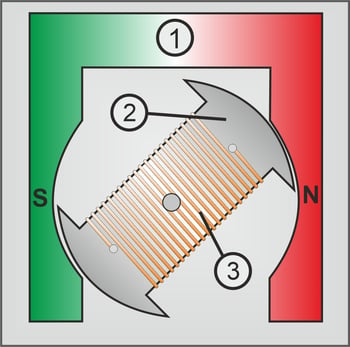
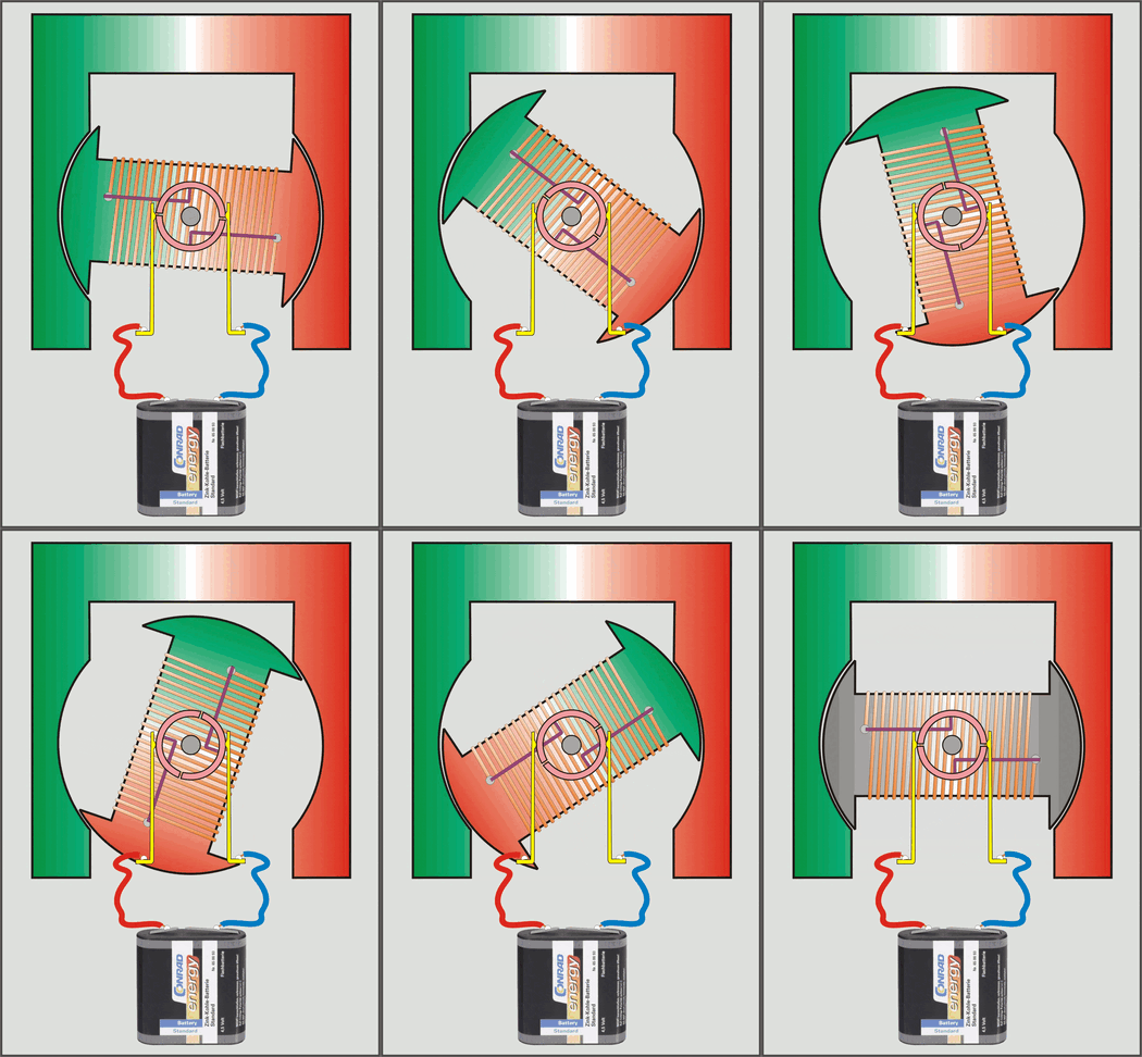
In order to build an electric motor, a permanent magnet (1) of a specific design is first required.
A rotating iron core (2) is mounted between the poles of the permanent magnet, around which a coil of insulated copper wire (3) is wound.
Effect of magnetic force
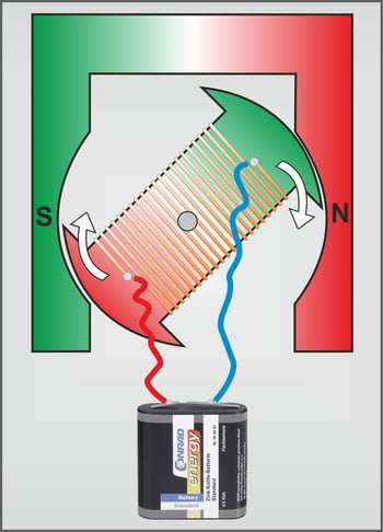
When direct current flows through the coil, the coil builds up a magnetic field and the iron core becomes an electromagnet. The polarity of the electromagnet, i.e. the alignment of the north and south poles, depends on the direction of the current in the coil.
Origin of the rotational movement
However, in order for the electromagnet to continue rotating continuously, the magnetic alignment must be reversed.
This is done by simply changing the direction of the current in the coil. This task is performed by a slip ring (collector) connected to the coil, to which the two contacts with the supply voltage are connected.
Shortly before the electromagnet reaches the optimal alignment, the current is switched off via the slip ring and immediately switched on again with reverse polarity (see animated image).
The reverse current direction also reverses the magnetic field of the electromagnet. Now, identical magnetic poles face each other and repel each other with all their force.
The armature continues to rotate until, after a quarter turn, the unequal magnetic poles attract each other again. Shortly before the optimum alignment is reached, the current is reversed again and the process begins anew.
Note: Direction of rotation
The direction of rotation of the motor depends on the polarity of the battery (DC voltage) at the sliding contacts. If the polarity of the voltage is reversed, the direction of rotation of the motor will also change. The rotational speed depends on the operating voltage. The higher the voltage, the faster the motor rotates. However, the maximum permissible operating voltage of the motor must not be exceeded.
The word stator is derived from the Latin word “stare,” meaning to stand still. The stator or stand is the immovable part of an electric motor.
The stator can consist of either a permanent magnet or an electromagnet.
In an internal rotor, the stator is firmly connected to the outer motor housing. In an external rotor, the stator is located inside the motor.
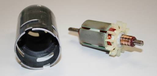
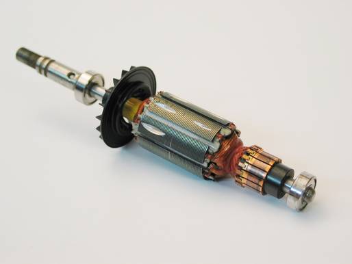
The rotating part of an electric motor is called the rotor or armature.
The rotor usually consists of a motor shaft, the armature made of sheet iron, an armature coil with different windings, and a slip ring for power transmission. In addition, impellers are often attached to the armature to cool the motor during operation.
Alternatively, permanent magnets in a round design can be used instead of the rotor coil. In this case, the slip ring and the sliding contacts are not required. The motor coil is then integrated into the stator. These brushless motors are very popular in model making, but cannot be operated with direct current.
An electric motor with only a 2-pole armature would have a significant disadvantage. In the position in which the coil is reversed, the contacts on the slip ring are temporarily disconnected from the coil.
However, when the power supply is switched off, 2-pole motors tend to remain in exactly this position. The reason for this is the residual magnetism of the armature.
When the power supply is switched on again, the motor cannot start. For this reason, rotors with three or more poles are used in practice.
These armatures are also known as drum armatures.
Regardless of the position of the armature, as soon as the voltage is switched on, current flows through the armature coils. The motor thus starts reliably.
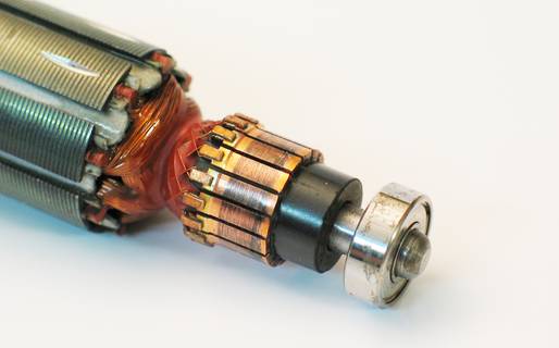
Since the armature coil in the rotor rotates, it cannot be hard-wired from the outside. Contact is made via a slip ring. The slip ring on the armature is also called a commutator or current reverser.
The slip ring supplies the armature coils with current in the correct direction. However, commutation also has significant disadvantages. It is subject to wear and tear, and brush fire occurs at the sliding contacts.
To keep the effects as low as possible even at high current transmission, sliding contacts or motor brushes made of graphite are used.
In some cases, metallic components such as copper, molybdenum, or silver are added to the graphite.
The electric motors discussed and shown so far have an armature with a current conductor winding and an iron core. As beneficial as the bundling and amplification of the magnetic field by the iron core may be, there are also some disadvantages that must be accepted.
The constant magnetic polarity reversal consumes energy and generates harmful eddy currents. To avoid these undesirable eddy currents as much as possible, the iron core is constructed from individual electrical steel discs that are electrically insulated from each other.
Since the iron core is magnetized by the permanent magnet, the motor has what is known as cogging torque. The cogging torque is clearly noticeable when a powerful electric motor with a three-pole drum armature is turned by hand. In addition, the considerable mass of the iron core also causes a certain amount of inertia when the motor starts up and when the speed changes.
Coreless bell-type armature motor
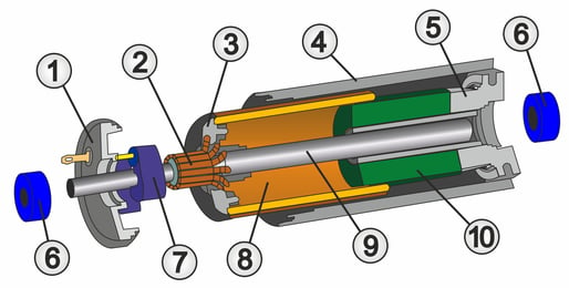
In a bell-type armature motor, on the other hand, the armature consists of a specially shaped, self-supporting coil (8) without an iron core.
The coil is connected to the collector (2) and the motor shaft (9) via the collector plate (3).
A permanent magnet (10) is located in the center of the coil, with the motor housing (4) serving as the magnetic return path.
This mechanical design gives the bell-type armature motor decisive advantages:
Advantages and disadvantages of bell-type armature motors
No iron losses
The absence of an iron core also eliminates losses in the iron core. This significantly increases efficiency, which is also reflected in lower no-load current. The torque is proportional to the current, and extremely strong permanent magnets can be used because there is no iron core that could otherwise become magnetically saturated.
No cogging torque
Since there is no iron core, the motor also has no cogging torque. This enables smooth running even at low speeds. At high speeds, the motor generates less vibration and runs more smoothly. Since the rotor also stops in any position, sensitive controls are easily possible.
No inertia
Compared to a conventional motor with an iron core, the very low armature mass allows a bell-type armature motor to start up very quickly and react dynamically to speed changes. In addition, the motor design enables a compact construction and high torque in relation to the motor size.
Lower inductance
The absence of an iron core means that the inductance of a bell-type armature motor is lower, resulting in less brush sparking. This reduces wear and tear and makes it easier to suppress interference in the motor.
Low thermal load capacity
On the other hand, a bell-type armature motor also has negative characteristics. For example, the thermal load capacity of the armature is not as high because there is no iron core to absorb excess heat energy in this case.
There are now many different types of electric motors. The most significant difference between the individual types is the power supply. The design specifies whether the motor must be powered by direct current, alternating current, or three-phase current.
The required magnetic fields are also generated in different ways in the respective motors. In addition to strong permanent magnets, electromagnets are also used, depending on the intended application. In the simplest case, a coil of copper wire is wound around an iron core made of sheet metal plates to generate the required magnetic field.
The differences between the most common types of electric motors and the various designs are described in more detail in the following sections.
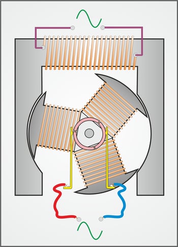
As already mentioned, DC motors are operated with a permanent magnet as the stator. If the operating voltage of the rotor is reversed, the direction of rotation of the motor changes.
If a DC motor were to be operated with an AC voltage of 50 Hz, the rotor would not be able to change its direction of rotation 100 times per second. In this case, the rotor would not rotate, but would merely emit a humming noise.
To avoid this, the magnetic field of the stator must change at the same 50 Hz rhythm as that of the rotor.
In practice, this is achieved by using a package of sheet metal strips equipped with an excitation winding instead of a permanent magnet for the stator. The magnetic fields of the stator and rotor now change synchronously 100 times per second, allowing the motor to run continuously in one direction.
If the stator winding and the armature winding are connected in series (series connection), the motor is referred to as a series motor or main connection motor. These types of motors are used in household appliances such as mixers or vacuum cleaners. If the stator winding and the armature winding are connected in parallel, the motor is also referred to as a shunt motor.
For higher power requirements, e.g. in industry, production or electrical machines, electric motors are not operated with alternating voltage, but with three-phase alternating current or “three-phase current”. In practice, squirrel-cage rotors have proven to be ideal, as they have virtually no wearing parts and are extremely low-maintenance.
What exactly is three-phase current?
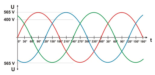
The energy supplier provides three phases (live wires) for the power supply to buildings.
The voltage difference between one of the three phases (L1, L2, or L3) and the neutral conductor (N) is used for the electrical installation. In this case, the voltage is 230 V.
Since the three phases are shifted by 120° in relation to each other, a voltage difference of 400 V can be measured between the phases.
How a three-phase motor works
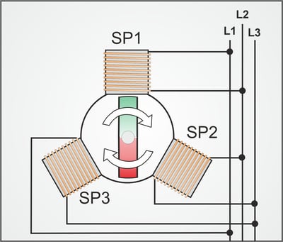
When three wire coils (SP1 to SP3) are arranged in a triangle and connected to the three phases, the coils generate a magnetic field that “rotates” in time with the mains frequency.
All that remains is to mount a magnetic rotor in the center of the three coils, which is “carried along” by the rotating magnetic field.
As a result, a three-phase motor does not require a commutator, which significantly simplifies its design.
This also reduces maintenance and service work to a minimum.
Structure of a three-phase motor
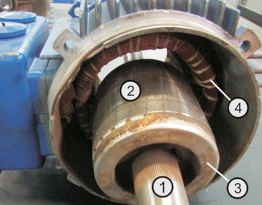
The rotor consists of a shaft (1) with circular iron laminations (2) that are insulated from each other. Several solid metal bars (not visible in the image) are embedded in the rotor and serve as current conductors. On both sides of the rotor, the metal bars are conductively connected (short-circuited) to a metal plate (3). The resulting conductor cage gave rise to the name cage rotor or short-circuit rotor.
The magnetic field of the stator coils (4) induces a current in the conductors of the rotor cage, which in turn also generates a magnetic field. The mutual influence of the magnetic fields causes the rotor to rotate.
The direction of rotation depends on the sequence of phase shift on the connection lines and can be changed by swapping two of the three connection lines.
Star/triangle connection
Due to the high starting current, powerful three-phase motors are started in star connection (sketch A). This means that two of the three coils (SP1 - SP3) are always connected in series between the phases. Once the motor has reached its speed, it switches to delta connection (sketch B) so that the motor can deliver its full power.
The speed depends on the mains frequency and the number of coil pairs. A motor with four coil pairs has a fixed speed of 750 revolutions per minute (50 Hz x 60 seconds/minute = 3000 : 4 coil pairs) according to the following formula.
If speed control is required, frequency converters must be used. Frequency converters change the fixed frequency of the alternating voltage in the supply network to a variable frequency for the connected motor. Since the rotor lags behind the magnetic field of the stator and is not synchronous, these motors are also referred to as asynchronous motors. In contrast, in a synchronous motor, the rotor rotates synchronously with the rotating field of the stator. However, synchronous motors are significantly more complex in design.
The reluctance force is also known as Maxwell's force. It is always directed in such a way that magnetic resistance is reduced and inductance increases.
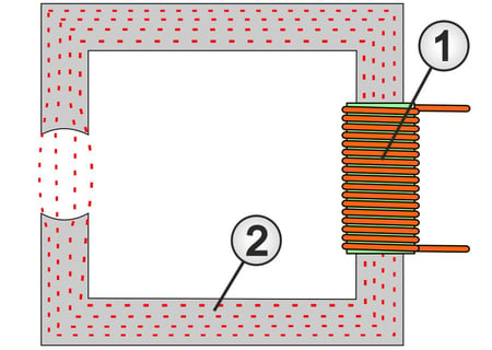
This can best be described using a coil (1) with an open rectangular ring (2) made of sheet iron. When current flows through the coil, it creates a magnetic field.
The magnetic field lines (shown in red) are concentrated and conducted by the rectangular iron core.
However, the gap in the open iron ring represents a significant magnetic resistance.
Use of reluctance force
Functional principle of the reluctance motor
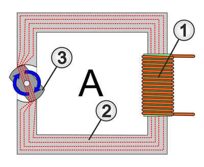
A reluctance motor works on exactly the same principle. Two poles of the stator form an open magnetic core ring, and two poles of the rotor act as a movable part that closes the magnetic ring.
Structure of a reluctance motor
A reluctance motor is similar in design to a three-phase motor. The windings of the coils, which generate the required magnetic field, are located in the outer, stationary part (stator).
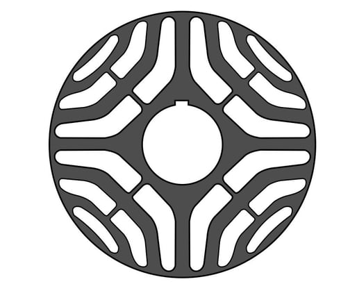
However, the rotor of a reluctance motor is not designed as a squirrel cage. Instead, the rotor aligns itself with the magnetic field lines at the poles of the stator.
To this end, it consists of many layers of iron sheets stacked on top of each other, which have a very specific shape. The metal bars serve as conductors for the magnetic flux, and the spaces between them act as an insurmountable barrier for the magnetic field lines.
Thanks to its simple design, the motor can be manufactured cost-effectively, and because there are no conductors in the armature or rotor, there are no conduction losses. This allows the motor to operate with maximum efficiency. Particularly in the partial load range, the reluctance motor has a significantly higher efficiency than conventional three-phase motors with squirrel-cage rotors.
Function of a reluctance motor
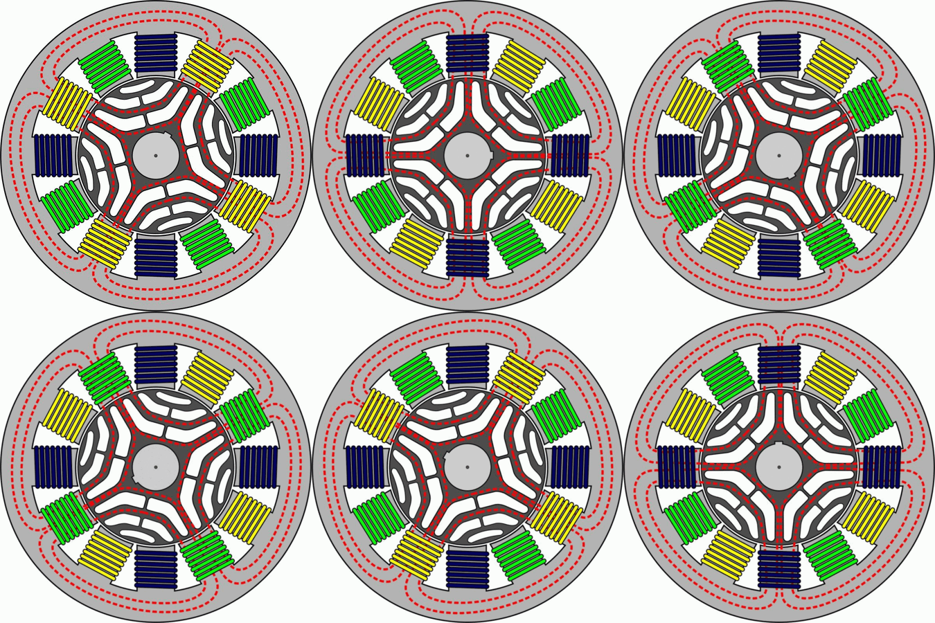
In order to clearly explain the operating principle of a reluctance motor, only 12 coils/poles in the stator are shown in the example. In practice, however, far more coils are used, which means that the poles are much closer together. In this case, all of the rotor's bars conduct the magnetic field lines.
The coils of the same color are connected to each other and are always controlled together. As soon as current flows through the blue coils, the magnetic fields shown in the image (red lines) build up according to the winding direction of the coils. The rotor then immediately aligns itself with the magnetic fields.
When the blue coils are switched off and the yellow coils are switched on, the rotor realigns itself and rotates slightly clockwise. The same happens when the yellow coils are switched off and the green coils are switched on.
In practice, the coils are controlled using a frequency converter. This allows the direction of rotation of the rotor and the speed of the rotating field to be individually adjusted and regulated. Since the rotor always aligns itself immediately with the magnetic field, it runs synchronously with the rotating field.
Reluctance motors are used for fans, pumps, and machine drives. Another major area of application for reluctance motors is electric vehicles. In this case, powerful permanent magnets are also used in the rotor to increase torque and efficiency. These motors are then referred to as hybrid motors and are widely used in smaller versions as stepper motors.
A capacitor motor is an AC motor designed for lower power ratings. It belongs to the group of asynchronous motors and is powered by 230 V AC voltage. The design of a capacitor motor is based on a squirrel cage motor with a cage rotor. However, the capacitor motor has only one main winding (SP1) and one auxiliary winding (SP2) that is mechanically offset by 90°. In order for the rotor to be set in motion, the voltage increase in the auxiliary winding must be time-delayed. This is achieved by connecting a capacitor (K) in series with the auxiliary winding. The reactive current, which is generated by the constant alternating charging of the capacitor at a 50 Hz rhythm, causes a phase shift of 90° in the auxiliary winding and thus starts the motor.
Due to the wiring of the two coils and the capacitor, a direction of rotation was specified during the production of the motor. The motor always maintains this direction of rotation, regardless of the position in which the power plug is inserted into the socket.
Our practical tip: Causes of malfunctions
Capacitor motors are just as robust, simple, and low-maintenance as three-phase motors. For this reason, motor windings are rarely affected by electrical defects. In most cases, the capacitor is the cause of the malfunction. And best of all, in most motors, the motor capacitors can be replaced easily and inexpensively.
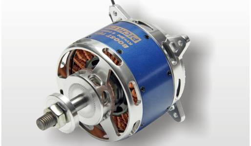
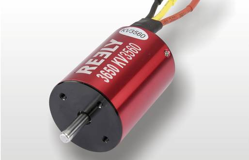
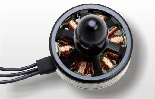
Brushless electric motors are essentially three-phase motors that are used as drives in control technology, as vehicle drives, and also in model making. Since the motors do not have carbon brushes, there is no brush fire that interferes with remote control technology or control electronics.
The motors differ in their design in terms of internal and external rotors.
Due to their design, internal rotors have high speeds and relatively low torque. External rotors, on the other hand, have high torque but not such high speeds.
In order for brushless electric motors to be used effectively, they require a special motor controller that converts the DC voltage of the drive battery into an artificial three-phase current. In model making, special brushless speed controllers (ESC = Electronic Speed Controller) are used for this purpose. The speed controller receives the control information on how fast the motor should run from the receiver.
To change the direction of rotation, it is sufficient to simply swap two of the three connection cables.
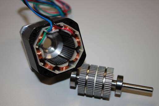
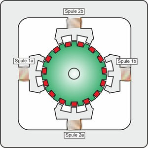
A stepper motor is essentially a brushless electric motor designed as an internal rotor.
Due to its design and control system, it is capable of performing defined rotational movements (step angles) of 1.8 degrees or less.
Stepper motors are powered by direct current, which must be switched to the motor coils in a precisely specified manner/sequence.
For this reason, stepper motors are controlled electronically. Stepper motors are available in different designs:
Reluctance stepper motor
In this motor, the rotor consists of a toothed soft iron core and an internally toothed stator. When the stator current is switched on, the rotor always aligns itself so that the teeth of the rotor and those of the stator face each other, thus creating the lowest possible resistance to the magnetic flux.
Permanent magnet stepper motor
In a permanent magnet stepper motor, the rotor consists of a strong magnet that aligns itself with the magnetic field of the stator. In a permanent magnet stepper motor, the possible number of poles is limited, which also leads to a limited resolution of the rotational steps.
Hybrid stepper motors
Hybrid stepper motors combine the technology of reluctance and permanent magnet stepper motors. This results in a high-torque stepper motor with high step resolution.
How stepper motors work
A bipolar stepper motor has two coils, each with two connections. Consequently, bipolar stepper motors have four connection cables that are routed to the outside. In a unipolar stepper motor, the two coils each have additional center taps, which are also routed to the outside. This is why unipolar stepper motors have six connection cables.
In principle, however, it does not matter whether the coils are reversed in a bipolar stepper motor or whether one half-coil is supplied with current alternately in a unipolar stepper motor. The basic mode of operation is always the same.
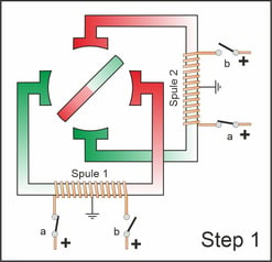
The following image shows how a unipolar stepper motor works in full-step mode, in which two coils are always supplied with current (steps 1–4).
Stepper motor in full step mode
In the example shown, the motor has four poles and the rotor has two poles, resulting in a 90° rotation with each step. Since two coils are always supplied with power at the same time, the torque of the rotor is correspondingly high.
Stepper motor in half-step mode
In half-step mode, one coil is always switched off between full steps. With the same design, this doubles the number of steps. However, the torque is lower in half-step mode because the magnetic force on the rotor is also lower.
Structure of a stepper motor
With the appropriate design, it is possible to implement a commercially available stepper motor with, for example, 200 steps per revolution.
This results in a step angle of 1.8° per step.
A microcontroller controls the stepper motor, controlling the sequence of steps according to the requirements of the application.
A motor driver handles the switching functions of the stator coils and provides the necessary current.
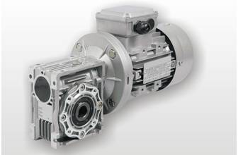
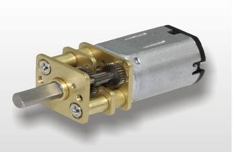
A gear motor consists of either a DC or AC motor with a gearbox flanged onto it. The gearbox reduces the speed of the motor while increasing the torque. Gear motors are primarily used in conveyor technology and mechanical engineering when slow movements and high power development are required. However, gear motors are also used in model making, e.g. as drive motors for tracked vehicles. Planetary gears, worm gears, or spur gears are the preferred gear designs.
Depending on the required power and application, gear motors use DC motors, AC motors, and three-phase motors.
