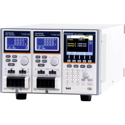
Meets all your requirements for a high-speed load simulation
The PEL-2004a and PEL-2002a are multi-channel programmable DC loads with modular structure. The PEL-2000A series was developed to meet the progressive shift toward high-speed operation in today's semiconductor market. Just like power supply units, DC-DC converters and batteries that drive semiconductor circuits to follow this shift have become necessary for power design, quality testing and characteristic certification with high-speed power loads. The PEL-2000A series consists of two types of mainframes and 4 types of load modules to flexibly meet the requirements of users. Each load module combination can be used with a mainframe to adapt a test system based on the number of channels and the maximum load voltage, voltage and current of each channel. Multiple loads can be connected in parallel to provide higher power to test higher power outputs. This flexibility reduces the investment required for future projects with different power requirements. The PEL-2004a is a 4-slot mainframe with a master control unit for accommodating 4 load modules, while the PEL-2002a is a 2-slot mainframe with master control unit for 2 load modules. If the PEL-2004a is configured with 4 350 watt load modules each, the PEL-2000A series can reduce power up to 1.4 kVA.
For higher load capacities, mainframes can be connected in parallel with standard MIL 20-pin connectors. Max. 5 mainframes, including one master and 4 slaves, can be connected together to provide a total load capacity of 7kW for high-current and high-performance applications. With 4 double-channel load modules, the PEL-2004a is able to test 8 supply outputs simultaneously. The sequence function allows each channel to change its load peak according to a predefined sequence at a speed of up to 100 s per step. Each sequence can run simultaneously under the control of a clock. This is one of the strongest features of the PEL-2000A series, since it is able to realistically simulate a power supply with several outputs. In dynamic mode, the load current or load resistance pulses between two preset levels at a specified speed of up to 25 s per step. This is often used as a standard test procedure to check the response of a power supply to rapid load changes. Remarkably, multiple load channels can be connected in parallel to run dynamic tests synchronously under a single clock. This Parallel Dynamic functionality provides the flexibility to perform dynamic tests for high performance power without the need for additional high performance load.
The PEL-2000A series has a number of protection modes: Over-current protection (OCP), over-voltage protection (OVP), over-load protection (OPP), over-voltage protection (RVP) and under-voltage protection (UVP). The protection modes are useful to protect both the load modules and the test specimens. A buzzer can be set if a protection setting has been triggered. If a protection mode has been triggered, the charging unit displays an alarm and stops the lowering of current/voltage. If a load unit is operated in CR or CV mode, the unit may require overcurrent protection to prevent excessive current from being reduced. The overcurrent protection stops the lowering of more current at the load than the recommended limit and prevents burn-out damage to the load. Overvoltage protection is used to limit the height of the voltage sensor. When the OVP is triggered, the PEL-2000A series stops the sinking voltage. Overload protection is used when the input power exceeds the specifications of the load. When OPP is triggered, the power stops being reduced. The back-voltage protection prevents back-voltage damage on the PEL-2000A series up to the specified nominal power. If the reverse voltage protection has been triggered, an alarm sounds until the reverse voltage is removed. Under-voltage protection switches the load off when the voltage drops below a set limit. The Go/NoGo function is available to continuously monitor test results. If a test result exceeds a preset limit, a "No Go" message will appear on the display and a "No Go" signal can be sent via the D-SUB interface for external device control. This Go/NoGo function is available for CC mode, CV mode and CR mode. In "Program" mode, 12 programs, each containing 10 panel setup memories, can be edited to create repetitive test routines. Once a program has been run, the results of all test steps are displayed on the screen along with the Go/NoGo judgments. For external control and system configuration, the PEL-2000A series comes standard with USB and RS-232 interfaces and GPIB as an option. The LabVIEW driver and Data Logging PC software are supported for all available interfaces. Each channel has an analogue control/monitoring connector on the rear panel to switch the load on and off and to monitor the load current and load externally.
This text is machine translated.