• All things technology
  • Delivery within Europe
  • Right to Cancel applies
  • Specialist retailer since 1923

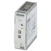
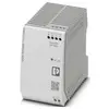
Phoenix Contact 2904627 Power supply unit Consumption (standby) 1 W 48 V DC 20 A 1217 VA No. of outputs:1 x Content 1 pc

Image similar
Datasheet (PDF)
EAN:
Part number:
Item no:
Unavailable

Sales and shipping:
Conrad ElectronicTerms & Conditions

Technical specifications

  • Product family: QUINT Power
  • Push-in connection
  • Width 120 mm
  • Height: 130 mm
  • Depth: 125 mm
  • Ambient conditions: Environmental conditions
  • Protection class: IP20
  • Ambient temperature (operation): -25 °C ... 70 °C (> 60 °C DERATING 2.5 %/K)
  • Ambient temperature (storage/transport): -40 °C ... 85 °C
  • Standards/regulations EN 61000-4-10
  • Mounting type: Rail mounting
  • Insulation properties: Insulation properties
  • Overvoltage category: Overvoltage category
  • Pollution level: 2
  • Vibration (operation): 5 Hz ... 100 Hz resonance search 0.7g, 90 min., resonance frequency 0.7g, 90 min.  (In accordance with DNV GL, class A)
  • 5 Hz ... 100 Hz resonance search 2.3g, 90 min., resonance frequency 2.3g, 90 min.  (According to DNV GL class C) fitted with UWA 130 - 2901664
  • Stripped length: 10 mm
  • Conductor cross-section flexible min.: 0.5 mm²
  • Conductor cross-section flexible max.: 1.5 mm²
  • Conductor cross-section rigid min.: 0.5 mm²
  • Conductor cross-section rigid max. 1 mm²
  • Mounting position: Horizontal mounting rail NS 35, EN 60715
  • Tightening torque min. 1.2 Nm
  • Frequency range: 50 Hz ... 60 Hz
  • Protection class: I
  • Frequency: 50 Hz
  • Rated input voltage range: ± 260 V DC ... 300 V DC
  • Input voltage range: ± 260 V DC ... 300 V DC -13 % ... +30 %;520 V DC ... 600 V DC -13 % ... 30 % (mid-Point earted)
  • Switch-on current impulse: Typical 1.5 A at 25 °C
  • Switch-on current surge integral (I2t) < 0.06 A2S
  • Inrush current limiter 2 A (after 1 ms)
  • Mains failure bridging time: Typ. 26 ms (3x 400 V AC);typ. 26 ms (3x 480 V AC)
  • POWER CONSUMPTION 2.2 A (±260 V DC);1.9 A (±300 V DC)
  • Nominal power intake 1217 VA
  • Switch-on time typical: 300 ms (from SLEEP MODE)
  • Switch-on time < 1 seconds
  • Selection of suitable fuse for the input protection: 1x 6 A (10 x 38 mm, 30 kA L/R = 2 ms)
  • Efficiency: Type. 95.9 % (400 V AC);typ. 96.2 % (480 V AC)
  • Rated output voltage 48 V DC
  • Setting range of output voltage (USet): 48 V DC ... 56 V DC (power constant)
  • Nominal output current (IN): 20 A.
  • Static Boost (ISTAT.Boost): 22.5 A.
  • Dynamic boost (IDyn.Boost) 30 A (5 s)
  • Selective Fuse Breaking (ISFB) 105 A (15 ms)
  • MAGNETIC FUSE TRIGGERING A1...A20 / B2...B10 / C1...C6 / Z1...Z16
  • Short-circuit-proof: Yes
  • Idle: Yes
  • Regenerative resistance ≤ 60 V DC
  • Protection against overvoltage at output (OVP): ≤ 60 V DC
  • Remaining ripple: < 50 mV SS (at nominal values)
  • Rise time: < 1 s (Uout = 10 % ... 90 %
  • Series switching capability: Yes
  • No-load power Maximum < 6 W (400 V AC);< 6 W (480 V AC)
  • Load power rating max.: < 41 W (400 V AC);< 41 W (480  V AC)
  • POWER LOSS SLEEP MODE < 1 W (400  VAC);< 1 W (480  VAC)
  • Parallel switching capability: Yes, for redundancy and power increase
  • Safety (secondary side): Electronic;thermomagnetic;thermal
  • Input: 2 kV (test efficiency 4 - symmetric);4 kV (test efficiency 4 - asymmetric)
  • Output:1 kV (test efficiency 3 - symmetric);2 kV (test efficiency 3 - asymmetric)
  • Signal: 4 kV (test sharpness: 2 – unbalanced)
  • Default: Closed (Uout > 0.9 usset)
  • DIGITAL 24 V DC 1 A;30 V AC 0.5 A
  • Analogue: 4 mA ... 20 mA ±5 % (load ≤400 Ω)
  • Signal earth Sgnd: Reference potential for Out1, Out2 and Rem
  • Number of phases: 3
  • Insulation voltage input/output: 4 kV AC (type test);2.4 kV AC (routine test)
  • Switching frequency: 32.00 kHz ... 100.00 kHz (auxiliary converter stage);55.00 kHz ... 300.00 kHz (main converter stage);25.00 kHz ... 500.00 kHz (PFC level)
  • MTBF (IEC 61709, SN 29500): > 851000 h (25 °C);> 519000 h (40 °C);> 237000 h (60 °C)
  • Service life (electrolytic capacitors): Life expectancy (electrolytic capacitors)
  • Current 20 A
  • Temperature 25 °C.
  • Time 218000 h
  • Additional text: Testing degree of accuracy 2
  • Mounting dimensions
  • Protective coating: No.
  • Flammability class to UL 94 (housing / terminals): V0
  • Case material: metal
  • Design of the hood: Stainless steel X6Cr17
  • Execution of side parts: Aluminium
  • Operating height: ≤ 5000 m (> 2000 m, observe derating)
  • Climate class 3K3 (according to EN 60721)
  • Max. ass. Humidity (operating): ≤ 95% (at 25°C, no condensation)
  • Shock: 11 ms, 15 g, per direction of room (according to IEC 60068-2-27)
  • Temp code: T4 (-25 ... +70 °C | > 60 °C, DERATING 2.5 %/K)
  • EN 61010-1: II (≤ 5000 m)
  • EN 62477-1: III (≤ 2000 m)
  • CSA: CAN/CSA-C22.2 NO. 61010-1-12;CAN/CSA-C22.2 NO. 61010-2-201
  • SIQ: CB-SCHEME (IEC 61010-1, IEC 61010-2-201)
  • Electromagnetic compatibility: Conformity to EMC directive 2014/30/EU
  • Low Voltage Directive: Conformity to NSR Directive 2014/35/EU
  • EMC requirements for emission of interference EN 61000-6-3;EN 61000-6-4
  • EMC requirements for immunity EN 61000-6-1;EN 61000-6-2
  • Line-guided interference emission: Line-guided interference emission
  • Interference radiation: Interference radiation
  • DNV GL conductive emission of interference: DNV GL conductive emission of interference
  • DNV: Class B
  • DNV GL interference radiation: DNV GL interference radiation
  • Discharge of static electricity: Discharge of static electricity
  • Contact discharge 8 kV (test efficiency 4)
  • 15 kV (test efficiency 4)
  • Note: Criterion A: 0.5 / 1 period
  • Criterion B: 5 / 50 / 250 periods
  • Electromagnetic HF-field: Electromagnetic HF-field
  • Test field strength 1000 A/m
  • Fast Transients (Burst): Fast Transients (Burst)
  • Surge voltage load (SURGE): Surge current load (SURGE)
  • Conducted interference: Conducted interference
  • Input/output/signal: Asymmetrical
  • Voltage: 2.5 kV
  • Magnetic field with energy-technical frequency: Magnetic field with energy-technical frequency
  • Voltage dips: Voltage dips
  • Voltage dip 0%
  • Pulse-shaped magnetic field: Pulse-shaped magnetic field
  • Asymmetric conductive interference variables: Asymmetric conductive interference variables
  • 100 kHz testing level 1
  • Test level 2 1 MHz
  • 1.5 kHz 15 kHz (test level 3 4) test level
  • 15 kHz 150 kHz (test level 4 4) test level
  • Test level 5: 16.7 Hz 50 Hz 60 Hz 150 Hz 180 Hz (test efficiency 4)
  • Test level 6: 16.7 Hz 50 Hz 60 Hz (Test efficiency 4)
  • Dampened oscillating shaft: Dampened vibrating shaft
  • Input, output (test level 1): 100 kHz 1 MHz (test level 3 - balanced)
  • Input, output (test level 2): 10 MHz (test level 3 - unbalanced)
  • Input, output (test level 3): 100 kHz 1 MHz (test level 3 - unbalanced)
  • Signals (test level 1): 100 kHz 1 MHz (test level 3 - balanced)
  • Signals (test level 2): 100 kHz 1 MHz (test level 3 - unbalanced)
  • Dampened oscillating magnetic field: Damped oscillating magnetic field
  • Criteria: Criteria
  • Criterion A: Normal operating behavior within the defined limits.
  • Criterion B: Temporary impairment of the operating behavior, which the device itself corrects.
  • Criterion C: Intermittent impairment of the operating behavior that the device itself corrects or can be restored by operating the controls.
  • Surrounding temperature (startup type tested): -40 °C
  • TRACK APPLICATIONS: EN 50121-3-2 ;EN 50121-5;IEC 62236-3-2;IEC 62236-5
  • Control input (configurable) REM: Power output ON/OFF (SLEEP MODE)
  • AC operation: AC operation
  • Grid type: Star network
  • National mains voltage typical: 400 V AC;480 V AC
  • Voltage type of supply voltage: DC
  • Frequency range AC: 50 Hz ... 60 Hz -10 % ... +10 %
  • Frequency range (FN): 50 Hz ... 60 Hz -10 % ... +10 %
  • Protective circuit: Transient overvoltage protection | Varistor, gas deflector
  • Power factor (cos phi) 0.95
  • Selection of suitable fuse for the input protection: ≥ 1000 V DC
  • Leakage current against PE: < 3.5 mA;1 mA (550 V AC, 60 Hz)
  • DC-operation: DC-operation
  • Derating: > 60 °C ... 70 °C (2.5 %/K)
  • Control deviation: < 0.5 % (load change static 10 % ... 90 < %); 2 % (load change dynamic 10 % ... 90 < %, (10 Hz)); 0.25 % (input voltage variation ±10 %)
  • POWER OUTPUT 960 W;1080 W;1440 W.
  • Crest factor: Typ. 1.67 (400 V AC);typ. 1.63 (480 V/ AC)
  • Signal Out 1 (configurable): Signal Out 1 (configurable)
  • Signal Out 2 (configurable): Signal Out 2 (configurable)
  • Signal relay 13/14 (configurable): Signal relay 13/14 (configurable)
  • One-conductor/flexible clamping point with wire-end sleeve with plastic sleeve min.: 0.2 mm²
  • Single-conductor/flexible clamping point with wire-end sleeve with plastic sleeve max.: 0.75 mm²
  • One-conductor/clamping point flexible with wire-end sleeve without plastic sleeve min.: 0.2 mm²
  • Single-conductor cable/clamping point flexible with wire-end sleeve without plastic sleeve max.: 1.5 mm²
  • Wire cross section AWG min 20
  • Conductor cross-section AWG max. 16
  • Tightening torque max. 1.5 Nm
  • Signal output: Signal output
  • Pout: > 100 % (LED is amber, output power > 960 W);> 75 % (LED is green, output power > 720 W);> 50 % (LED is green, output power > 480 W)
  • Uout: > 0.9 x USet (LED lights up green);< 0.9 x USet (LED flashes green)
  • Insulation voltage output/PE: 0.5 kV DC (type test);0.5 kV DC (routine test)
  • Insulation voltage input/PE: 3.5 kV AC (type test);2.4 kV AC (routine test)
  • Environmental Protection Directive: RoHS Directive 2011/65/EU;WEEE;Reach
  • Installation distance right / left 5 mm / 5 mm
  • Installation distance above/below 50 mm / 50 mm
  • Standard - limitation of mains harmonic currents EN 61000-3-2
  • Standard - Electrical safety: IEC 61010-2-201 (SELV)
  • Standard - safety extra-low voltage: IEC 61010-1 (SELV);IEC 61010-2-201 (PELV)
  • Standard - Safe isolation: IEC 61558-2-16;IEC 61010-2-201
  • Standard - safety for measurement, control, regulation and laboratory devices: IEC 61010-1
  • Standard - transformer safety EN 61558-2-16
  • Charging according to DIN 41773-1
  • Approval - requirement of the semiconductor industry with regard to mains voltage drops: SEMI F47-0706, EN 61000-4-11
  • EN 61558-2-16: II (≤ 4000 m)
  • UL approvals: UL listed UL 61010-1;UL 121201 & CSA C22.2 No. 213-17 Class I, Division 2, Groups A, B, C, D T4 (hazardous location)
  • EMC requirements for power supply: IEC 61850-3 (G,H);EN 61000-6-5 (switchgear)
  • Harmonic currents: Harmonic currents
  • Flicker: Flicker
  • Number of periods: 0.5 / 1 / 5 / 50 / 250 periods
  • Dampened sine vibrations (ring wave): Dampened sine-wave oscillations (ring wave)
Nominal input voltage

3 x 400 - 500 V/AC

Product type

Power supply unit

Min. input voltage

400 V AC

260 V DC

Input voltage (max.)

500 V AC

600 V DC

Max. output current

20 A

Output current (max.) - rounded

20 A

1217 VA

Output type (power supply units)

Adjustable

Phases

3

Output voltage (nominal)

48 V DC

No. of outputs

1 x

Connection

Screws

Push-in spring-loaded terminal

Dim

(L x W x H) 125 x 120 x 130 mm

Output voltage (max.)

56 V DC

Output voltage (min.)

48 V DC

Operating temperature (max.)

70 °C

Max. operating temperature (derating)

70 °C

Min. operating temperature (derating)

60 °C

Operating temperature (min.)

-25 °C

Manufacturer part #

2904627

Content

1 pc(s)

MTBF

851000 h

PSU features

Adjustable voltage output

Width

120 mm

Height

130 mm

Length

125 mm

IP20

Max. temperature

70 °C

Min. temperature

-25 °C

Type

QUINT4-PS/3AC/48DC/20

Consumption (standby)

1 W

Efficiency

95.9 %

Depth

125 mm

Recess height

130 mm

UKCA

yes

Documents & Downloads

Datasheet

Datasheet 3579825 Phoenix Contact 2904627 Power supply unit Consumption (standby) 1 W 48 V DC 20 A 1217 VA No. of outputs:1 x Content 1 pc

User & Safety Instructions

User & Safety Instructions 3579825 Phoenix Contact 2904627 Power supply unit Consumption (standby) 1 W 48 V DC 20 A 1217 VA No. of outputs:1 x Content 1 pc
Description

Primary clocked power supply QUINT Power, screw terminal, mounting rail, input 3-phase, output 48 V DC / 20 A

This text is machine translated.

What kind of DIN Rail PSUs are you looking for?