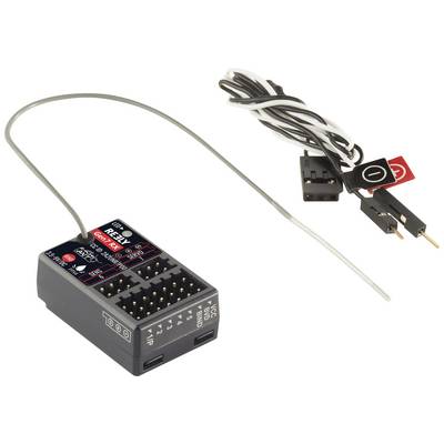
High-quality 7-channel receiverTo establish a connection with servos or other compatible components, the Reely model-built receiver provides seven channels for the output of the PWM signal. A PPM signal can also be output via channel 1.Variety of interfacesDuring normal operation, the voltage is at the BVD/VCC interface, a BVD harness can be connected to detect the battery voltage. In addition, connections are available for the binding process, for i-BUS sensors as well as a SERVO interface for the output of i-BUS or S-BUS signals. The i-BUS type channel extension is also supported here. ANT serves as the wireless network standard.
This text is machine translated.
Features
CH 1 to CH 7: For the output of the PWM signal (in addition, CH 1 can output the PPM signal)Can be connected to servos or other compatible componentsBVD/VCC: During the battery voltage detection process, a BVD harness is connected here. In normal operation, the voltage is at this interfaceBind interface: During the tying cycle, a tie wire is connected to this interfaceSENS interface: For connecting i-BUS sensorsSERVO interface: For the output of i-BUS or S.BUS signals and for supporting the channel expansion in i-BUS typeRF protocol: ANT
Scope of delivery
Receiver
User manual.
Description
High-quality 7-channel receiverTo establish a connection with servos or other compatible components, the Reely model-built receiver provides seven channels for the output of the PWM signal. A PPM signal can also be output via channel 1.Variety of interfacesDuring normal operation, the voltage is at the BVD/VCC interface, a BVD harness can be connected to detect the battery voltage. In addition, connections are available for the binding process, for i-BUS sensors as well as a SERVO interface for the output of i-BUS or S-BUS signals. The i-BUS type channel extension is also supported here. ANT serves as the wireless network standard.
This text is machine translated.
Features
CH 1 to CH 7: For the output of the PWM signal (in addition, CH 1 can output the PPM signal)Can be connected to servos or other compatible componentsBVD/VCC: During the battery voltage detection process, a BVD harness is connected here. In normal operation, the voltage is at this interfaceBind interface: During the tying cycle, a tie wire is connected to this interfaceSENS interface: For connecting i-BUS sensorsSERVO interface: For the output of i-BUS or S.BUS signals and for supporting the channel expansion in i-BUS typeRF protocol: ANT