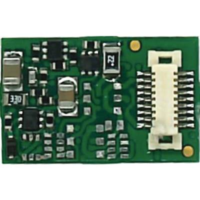
Number
Highlights & Details
Function decoder FD-Next with Next18 interface
- All functions of the Next18 interface including SUSI are assigned
- SMD-equipped circuit board
Technical specifications
- Data formats: Motorola-II (MM2/14, MM2/27b), DCC (DCC/14, DCC/28, DCC/128, DCC/SDF in accordance with NMRA and RCN standard)
- Formats for automatic registration of vehicle decoders: DCC-A in accordance with RCN-218 (can be switched off)
- RailCom feedback format to RCN-217 (can be switched off)
- Next18 interface to RCN-118
- 4 amplified function outputs (F0f, F0f, AUX1 and AUX2)
- 2 unamplified outputs (AUX5 and AUX6)
- Depending on the configuration: 2 unamplified outputs (AUX3 and AUX4) or 2 connections for the train bus, e.g. "Data (DATA)" and "Clock (CLOCK)" of the SUSI interface
- 1 connection for an external support capacitor (capacity 100 to 220 µF, voltage strength min. 35 V) or an external buffer circuit
- Power supply: 12 - 20 Volt digital voltage or analog travel transformer (DC voltage)
- Power consumption (without connected consumer load): Max. 20 mA
- Protection class: IP 00 (meaning: No protection against foreign objects, contact or water)
- Overload protection: Automatic switch-off of the decoder when the permissible motor or total current is exceeded
- Weight: approx. 0.6 g
- Decoder manufacturer
Tams
- Digital format
DCC
MM
- Decoder type
w/o cable
- Interfaces
w/o cable
- Selectable effects
Dimmer
Flashing
Reverse lamp
Lighting
Single flash
Kicks
Light signals
Interior lighting
- No. of outputs
4 x
- No. of switch modes
4
- Address range
DCC: 127 oder 10.239 | MM: 255
- Individually adjustable start & braking chracteristics
No
- Max. total current
1000 mA
- Suitable for analogue operation
Yes
- System auto-recognition
Yes
- Load control
Yes
- RailCom support
Yes
- SUSI interface
Yes
- Automatic pendulum movement
No
- Length
15 mm
- Width
9.5 mm
- Height
2.9 mm
- Age category
15 years and over
- Dim
(L x W x H) 15 x 9.5 x 2.9 mm
- Manufacturer part #
42-01194-01-C
- Product type
Decoder
Documents & Downloads
User & Safety Instructions
User & Safety Instructions 3207337 TAMS Elektronik 42-01194-01-C FD-Next18 Decoder w/o cable
Description
Digital mode in Motorola II-format:
Maximum 255 addresses
14 or 27B driving speeds
Functions F0 to F8 (F5 to F8 via second address)
Programming: Register
Digital mode in DCC format:
127 base addresses or 10,239 extended addresses
14, 28 or 128 speed settings
Functions F0 to F28
Programming: Configuration variables (direct programming on the programming track, DCC-compliant) or POM (Programming on Main = main track programming)
Analogue mode:
Analogue systems with DC travel transformer
Automatic analog detection
Can be switched off
Automatic processes
Speed-dependent switch-on and off. Application examples: Switching on and off of the high beam or the lighting of the driver's cab.
Automatic registration via DCC-A
Function outputs
Assignment of the functions to the outputs with function mapping according to RCN-227. Each function (F0 to F28, each separately for forward and reverse drive) can be assigned one or more outputs. In addition, there is the option of assigning the functions to a function other than "OFF" switch.
Assignment of the outputs to the functions: Freely selectable
Effects of the function outputs:
Direction-dependent switching
Patch light: When switching to marshaling mode, the marshaling locomotive signals are switched on and the signals for normal operation are switched off at the same time.
Inverted switching: When set to "on", the assigned output is switched off, when set to "off".
Flashing: By assigning the flashing function to 2 outputs and the function "inverted switching" to one of the two outputs, an alternating flashing is generated. The flashing frequency is set separately for each output.
Dimming: To reduce the voltage at the output. Application example: The lamps of older vehicles intended for analog operation can be dimmed and then do not need to be replaced after the decoder is installed.
Gradually dimming up and down: To gradually increase or decrease the voltage at the output: Application example: Simulation of old oil or light bulbs.
Fire simulation
On/off at a defined voltage (speed)
Triggering the functions:
Press the function keys / switch on/off the functions
Feedback with RailCom
RailCom-Sender according to RCN-217: Send the decoder address
Transmission of dynamic RailCom information: Reception statistics
Reading out the CVS
This text is machine translated.